506
Configuring PoE
Overview
IEEE 802.3af-compliant power over Ethernet (PoE) enables a power sourcing equipment (PSE) to supply
power to powered devices (PDs) through Ethernet interfaces over straight-through twisted pair cables.
Examples of PDs include IP telephones, wireless APs, portable chargers, card readers, Web cameras,
and data collectors. A PD can also use a different power source from the PSE at the same time for power
redundancy.
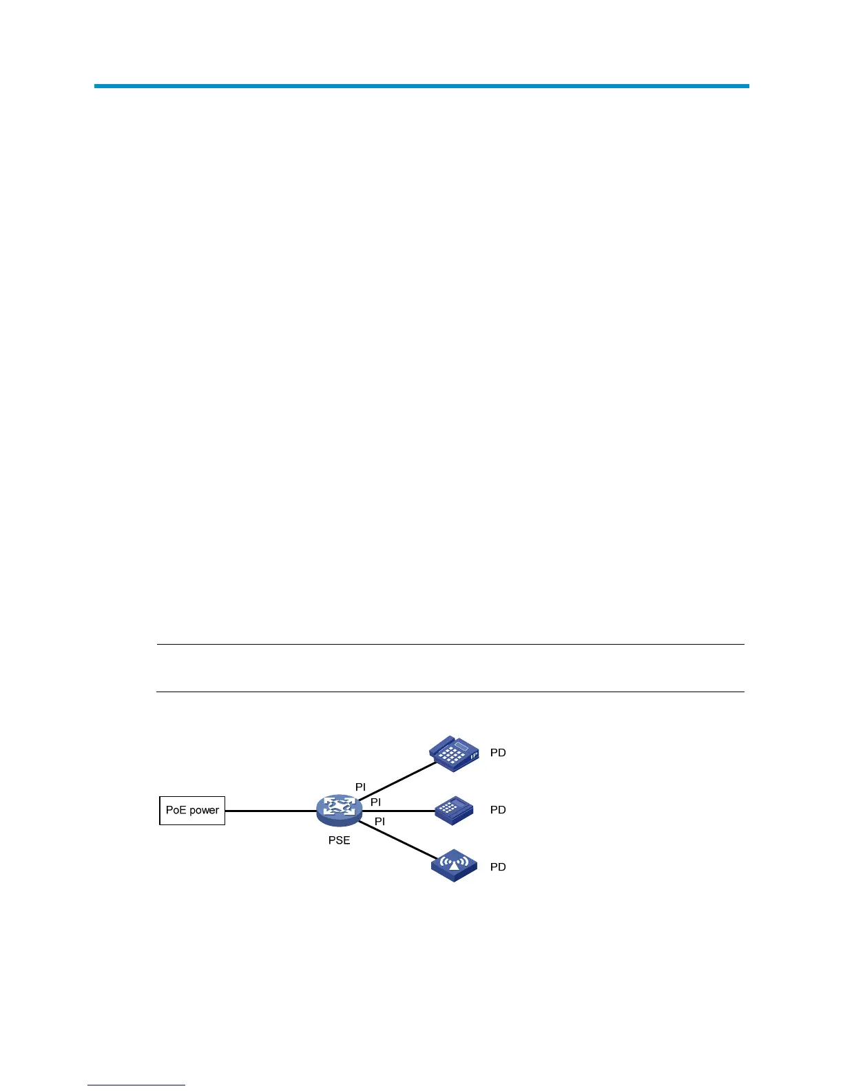
As shown in Figure 511, a P
oE system includes the following elements:
• PoE power—The entire PoE system is powered by the PoE power.
• PSE—The PSE supplies power for PDs. A PSE can examine the Ethernet cables connected to PoE
interfaces, search for PDs, classify PDs, and supply power to PDs. When detecting that a PD has
been disconnected, the PSE stops supplying power to the PD. A PSE can be built-in (Endpoint) or
external (Midspan). A built-in PSE is integrated into the device, and an external PSE is independent
of the device. The device has only one built-in PSE.
• PI—An Ethernet interface with the PoE capability is called PoE interface. A PoE interface can be an
FE or GE interface.
• PD—A PD receives power from the PSE. You can also connect a PD to a redundant power source for
reliability.
The PSE supplies power over category 3/5 twisted pair cable for a PoE interface in the following two
modes:
• Over signal wires—The PSE uses data pairs (pins 1, 2 and 3, 6) to supply DC power to PDs.
• Over spare wires—The PSE uses spare pairs (pins 4, 5 and 7, 8) to supply DC power to PDs.
NOTE:
The switching engine of the HP 830 switch supports only power over signal wires.
Figure 511 PoE system diagram
Configuring PoE
Before configuring PoE, make sure the PoE power supply and PSE are operating correctly. Otherwise,
either you cannot configure PoE or the PoE configuration does not take effect.
 Loading...