Aggregate interfaces on the device.
• On an HP 830 24-port PoE+ unified wired-WLAN switch switching engine, ports GE
1/0/29 and GE 1/0/30 are aggregated into interface BAGG1.
• On an HP 830 8-port PoE+ unified wired-WLAN switch switching engine, ports GE
1/0/10 and GE 1/0/11 are aggregated into interface BAGG1.
• On an HP 830 series PoE+ unified wired-WLAN switch controller engine, ports GE
1/0/1 and GE 1/0/2 are aggregated into interface BAGG1.
Port isolation configuration example
Network requirements
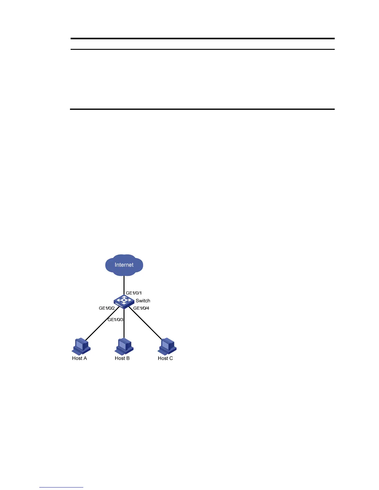
As shown in Figure 459:
• Campus network users Host A, Host B, and Host C are connected to GigabitEthernet 1/0/2,
GigabitEthernet 1/0/3, and GigabitEthernet 1/0/4 of Switch.
• Switch is connected to the external network through GigabitEthernet 1/0/1.
• GigabitEthernet 1/0/1, GigabitEthernet 1/0/2, GigabitEthernet 1/0/3, and GigabitEthernet
1/0/4 belong to the same VLAN.
Configure Host A, Host B, and Host C to access the external network while they are isolated from one
another on Layer 2.
Figure 459 Networking diagram
Configuring the switch
1. Add port isolation group 1:
a. Select Security > Port Isolate Group from the navigation tree.
b. Click the Group Setup tab.
c. Enter 1 in the Isolate group ID field.
d. Click Apply.
 Loading...