281
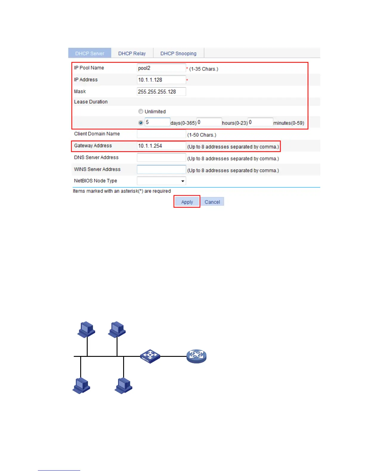
Figure 266 Configuring attributes for pool2
DHCP relay agent configuration example
Network requirements
As shown in Figure 267, VLAN-interface 1 on the DHCP relay agent (Switch A) connects to the network
where DHCP clients reside. The IP address of VLAN-interface 1 is 10.10.1.1/24 and the IP address of
VLAN-interface 2 is 10.1.1.1/24. VLAN-interface 2 is connected to the DHCP server whose IP address is
10 .1.1.1 / 2 4 .
The switch forwards messages between DHCP clients and the DHCP server.
Figure 267 Network diagram
Configuration procedure
1. Enable DHCP:
DHCP server
Switch A
DHCP relay agent
DHCP client DHCP client
DHCP clientDHCP client
Vlan-int2
10.1.1.2/24
Vlan-int1
10.10.1.1/24