278
s u b n e t 10 .1.1. 0 / 24 . S u b n e t 10 .1.1. 0 / 2 5 a n d 10 .1.1.12 8 / 2 5 c a n i n h e r i t t h e c o n f i g u r a t i o n o f s u b n e t
10 .1.1. 0 / 2 4 .
HP recommends that you configure up to 122 clients to obtain IP addresses from VLAN-interface 1 and
up to 124 clients to obtain IP addresses from VLAN-interface 9.
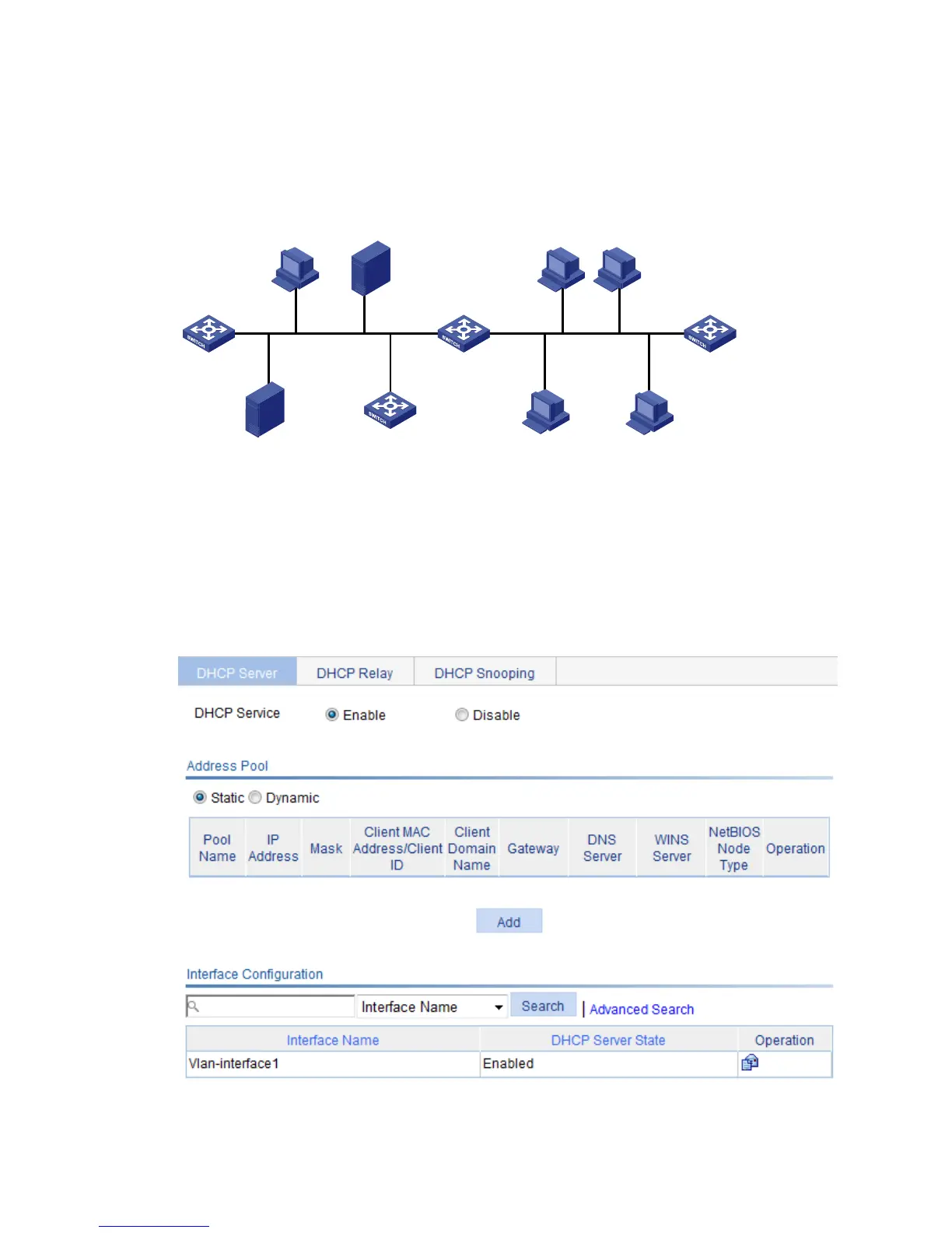
Figure 262 Network diagram
Configuring Switch A
1. Enable DHCP:
a. Select Network > DHCP > DHCP Server from the navigation tree to enter the DHCP Server
page.
b. Select the Enable option in the DHCP Service field.
Figure 263 Enabling DHCP
2. Configure the dynamic DHCP address named pool0:
WINS server
10.1.1.4/25
Client
Switch B
Client
DNS server
10.1.1.2/25
Switch A
DHCP server
Vlan-int9
10.1.1.129/25
Vlan-int1
10.1.1.1/25
Client Client
Client Client
Vlan-int2
Gateway A
10.1.1.126/25
Gateway B
10.1.1.254/25
 Loading...