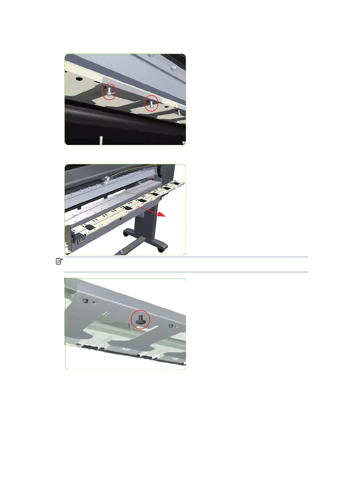
8. Remove two T-20 screws (Type M) from each Pinchwheel Subassembly (a 90° screwdriver is included
with the replacement Pinchwheel Assembly).
9. Remove the complete Pinchwheel Assembly (including the Cam and Cam Lever) from the printer.
NOTE: Before installing the new Pinchwheel Assembly, insert the plastic studs into each Pinchwheel
subassembly. This will make it easier to install the complete Pinchwheel Assembly.
Removing individual Pinchwheel Rollers
▲
To remove an individual Pinchwheel roller, push apart the metal part that secures the Pinchwheel roller
and then pull out the individual Pinchwheel roller.
392 Chapter 9 Printer part removal and installation ENWW
 Loading...