Operation Manual – VRRP
Quidway S3900 Series Ethernet Switches-Release 1510 Chapter 1 VRRP Configuration
Huawei Technologies Proprietary
1-13
1.4.2 VRRP Tracking Interface Configuration
I. Network requirements
Even when Switch A is still functioning, Switch B (with another link to connect with the
outside) can function as a gateway when the interface on Switch A and connecting to
Internet does not function properly. This can be implemented by enabling the VLAN
interface tracking function.
The VRRP backup group ID is set to 1, with configurations of authorization key and
timer.
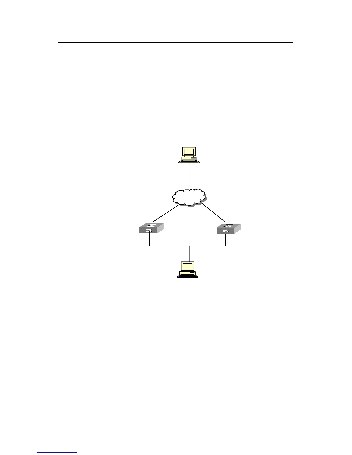
II. Network diagram
Virtual IP address: 202.38.160.111
LSW-A
Host A
202.38.160.3
-Vlan-interface2: 202.38.160.1
Internet
LSW-B
-
Vlan-interface2: 202.38.160.2
Host B
Virtual IP address: 202.38.160.111
Host A
202.38.160.3
-Vlan-interface2: 202.38.160.1
Internet
-
Vlan-interface2: 202.38.160.2
Host B
Vlan-interface3: 10.100.10.2
10.2.3.1
Virtual IP address: 202.38.160.111
LSW-A
Host A
202.38.160.3
-Vlan-interface2: 202.38.160.1
Internet
LSW-B
-
Vlan-interface2: 202.38.160.2
Host B
Virtual IP address: 202.38.160.111
Host A
202.38.160.3
-Vlan-interface2: 202.38.160.1
Internet
-
Vlan-interface2: 202.38.160.2
Host B
Virtual IP address: 202.38.160.111
LSW-A
Host A
202.38.160.3
-Vlan-interface2: 202.38.160.1
Internet
LSW-B
-
Vlan-interface2: 202.38.160.2
Host B
Virtual IP address: 202.38.160.111
Host A
202.38.160.3
-Vlan-interface2: 202.38.160.1
Internet
-
Vlan-interface2: 202.38.160.2
Host B
Vlan-interface3: 10.100.10.2
10.2.3.1
Figure 1-4 Network diagram for interface tracking configuration
III. Configuration procedure
z Configure Switch A.
# Configure VLAN 2.
<LSW-A> system-view
System View: return to User View with Ctrl+Z.
[LSW-A] vlan 2
[LSW-A-vlan2] port Ethernet 1/0/6
[LSW-A-vlan2] quit
[LSW-A] interface Vlan-interface 2
[LSW-A-Vlan-interface2] ip address 202.38.160.1 255.255.255.0
[LSW-A-Vlan-interface2] quit

 Loading...