Operation Manual – VRRP
Quidway S3900 Series Ethernet Switches-Release 1510 Chapter 1 VRRP Configuration
Huawei Technologies Proprietary
1-17
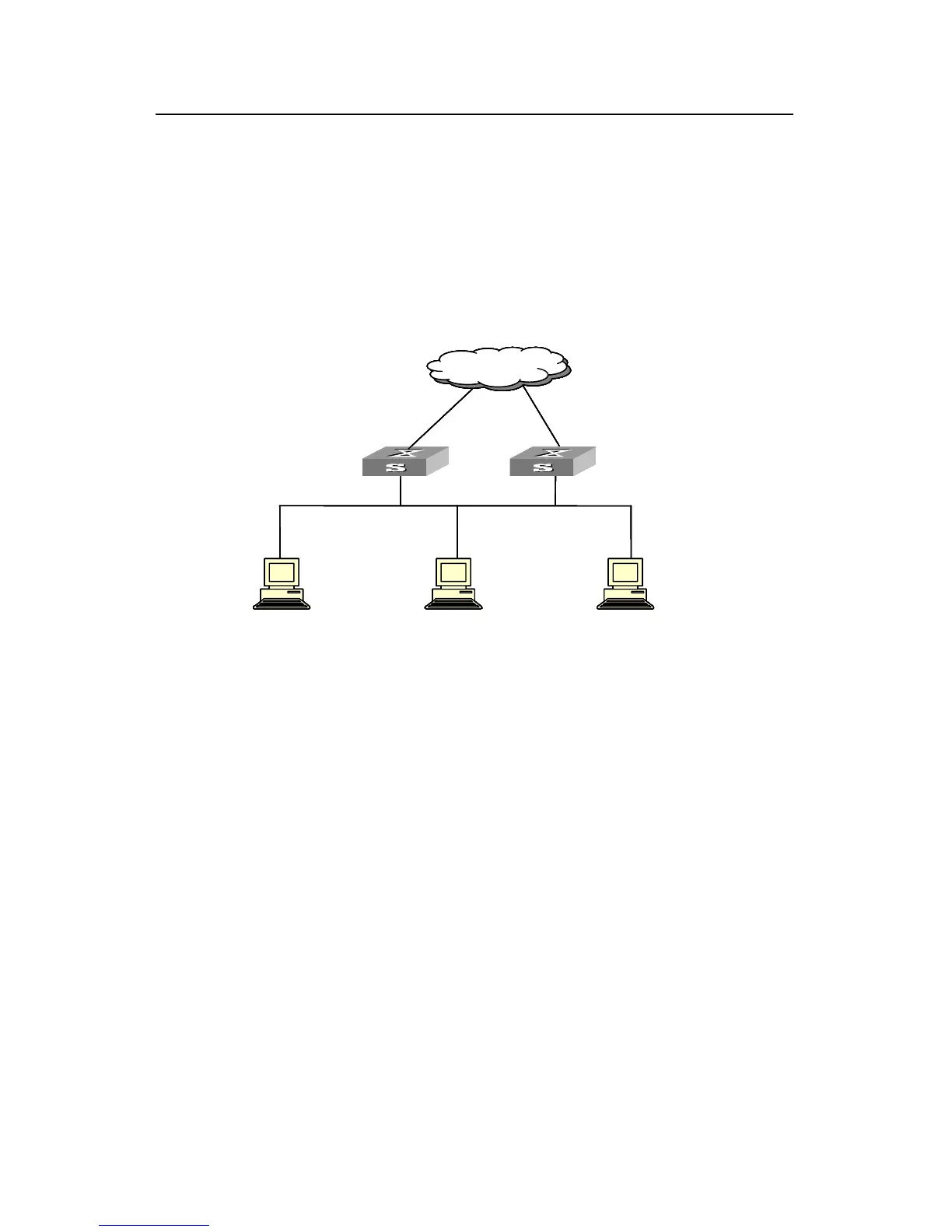
z The master switch is connected to the upstream network through its Ethernet1/0/1
port. The backup switch is connected to the upstream network through its
Ethernet1/0/2 port.
z The virtual router IP address of the backup group is 10.100.10.1.
z Enable the port tracking function on Ethernet1/0/1 port of the master switch and
specify that the priority of the master decreases by 50 when Ethernet1/0/1 port
fails, which triggers new master switch being determined in the backup group 1.
II. Network diagram
Ethernet
Mas ter
Host 1Host 2Host 3
10.100.10.7 10.100.10.8 10.100.10.9
Virtual IP address10.100.10.1
Network
Backup
Virtual IP address10.100.10.1
Actual IP address10.100.10.2 Actual IP address10.100.10.3
Netw ork
Ethernet
Mas ter
Host 1Host 2Host 3
10.100.10.7 10.100.10.8 10.100.10.9
Virtual IP address10.100.10.1
Network
Backup
Virtual IP address10.100.10.1
Actual IP address10.100.10.2 Actual IP address10.100.10.3
Netw ork
Figure 1-6 Network diagram for VRRP port tracking configuration
III. Configuration procedure
z Configure the master switch.
# Enter system view.
<Quidway> system-view
# Create VLAN 2.
[Quidway] vlan 2
[Quidway-vlan2] port Ethernet1/0/1
[Quidway-vlan2] quit
# Enter Ethernet1/0/1 port view and enable the port tracking function.
[Quidway] interface Ethernet1/0/1
[Quidway-Ethernet1/0/1] vrrp vlan-interface 2 vrid 1 track reduced 50

 Loading...