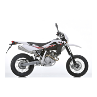
• Insert the tip (29) of stop buffer onto rod (32); it must be inserted so that the
side with the at is facing the case (30) and that you overcome the housing
of the wire (F).
• Insert the metal ring ( 27 ) into the proper seat( F )
• Bring the push rod ( 29 ) into contact with the stop ring.
• Insert the foot buffer ( 28 ); this must be inserted keeping the oil ow slots
towards the push rod.
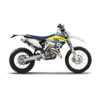
• Insert the upper nut ( 26 ) and tighten it on the push rod ( 29 ).
• Hold the nut ( 26 ) with a 18 mm spanner and tighten the push rod ( 29 ) up to
the required torque (see Table 1 - Tightening Torques), using a 17 mm span-
ner.
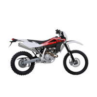
• Insert the guide spring ( 24 ) in the pumping element rod ( 32 ); the guide
spring must have the smaller diameter side towards the foot buffer.
• Screw the locknut ( 23 ) till the end without tightening.