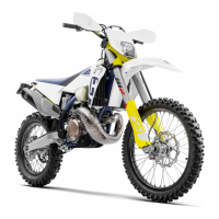
FUEL INJECTION SYSTEM
The fuel injection system is composed of fuel tank (1), electric pump (2), pipe (3)
and injector (4). The fuel in the tank is pumped by the pump. The pressurised
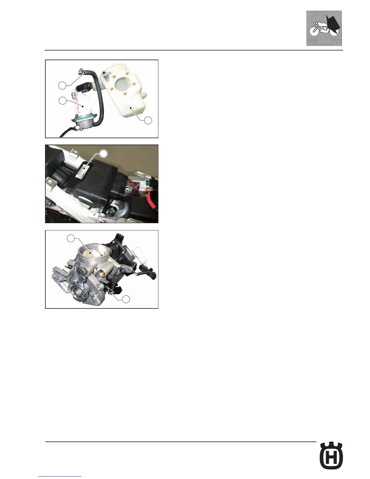
fuel ows into the injector installed on the throttle body (6). The electronic control
unit (5) located under the saddle signals the injector to open and a fan-shaped
spray of fuel is injected into the combustion chamber.
The parameters that play a role in determining proper fuel delivery under all
operating conditions are as follows:
- Air temperature in the intake manifold;
- Engine coolant temperature;
- Atmospheric pressure in the intake manifold (in current location and at cur-
rent altitude);
- Throttle opening;
- Battery voltage;
- Fuel injection pulse width;
- Ignition coil;
- Lambda sensor heater;
- Rich or lean combustion mixture (LAMBDA sensor);
"HUSQVARNA SERVICE TOOL" diagnostic software allows you to test the
components listed above in the event of a fuel injection system malfunction.
 Loading...