4.4 Address Configuration
B4-59
ME0384-4A
Chapter 4 Network Configuration
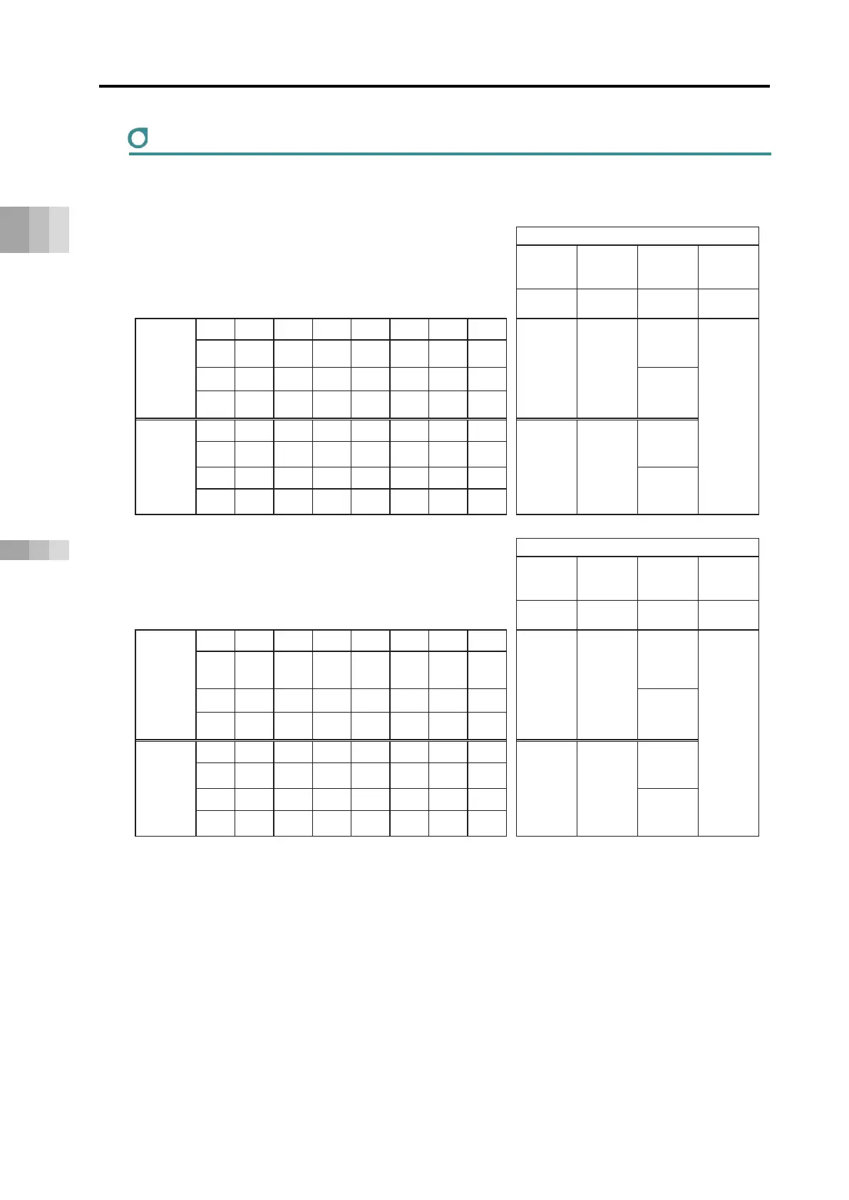
Gateway control/status signals
The first 2 words for each I/O in the gateway unit address configuration are signals for controlling
and monitoring the status of the gateway unit.
*
CC-Link IE
EtherNet/IP,
-
Gateway
Control
signal 0
b15 b14 b13 b12 b11 b10 b9 b8
RY 0* +0 +0
+0
MON
- - -
- - - -
+1
-
-
-
-
-
-
-
-
Gateway
Control
signal 1
RY 1* +1 +2
+3
CC-Link IE
EtherNet/IP,
-
Gateway
Status
signal 0
RX 0* +0 +0
+0
RUN LERC
ERRT
MOD
ALMH
ALML
-
SEM
b7 b6 b5 b4 b3 b2 b1 b0
+1
ALMC128
ALMC64
ALMC32
ALMC16
ALMC8
ALMC4
ALMC2
ALMC1
Gateway
Status
signal 1
b15 b14 b13 b12 b11 b10 b9 b8
RX 1* +1 +2
LNK15
LNK14
LNK13
LNK12
LNK11
LNK10
LNK9 LNK8
b7 b6 b5 b4 b3 b2 b1 b0
+3
LNK7 LNK6 LNK5 LNK4
LNK3 LNK2 LNK1 LNK0
*Address is the address relative to the gateway head.
CC-Link, CC-Link IE Field, and DeviceNet have word addresses while PROFIBUS-D P,
EtherNet/IP, and EtherCAT use byte addresses. PROFINET-IO uses 4-word module addresses.
The * in CC-Link and CC-Link IE Field bit register addresses is 0 to F.
For CC-Link and CC-Link IE Field, b10 to b15 are bA to bF. (Hexadecimal notation)
For PROFIBUS-DP, EtherNet/IP, and EtherCAT, b8 to b15 are b0 to b7. (Byte addresses)

 Loading...


