2.5 Connection Diagrams
A2-40
ME0384-4A
Chapter 2 System Configuration and Specifications
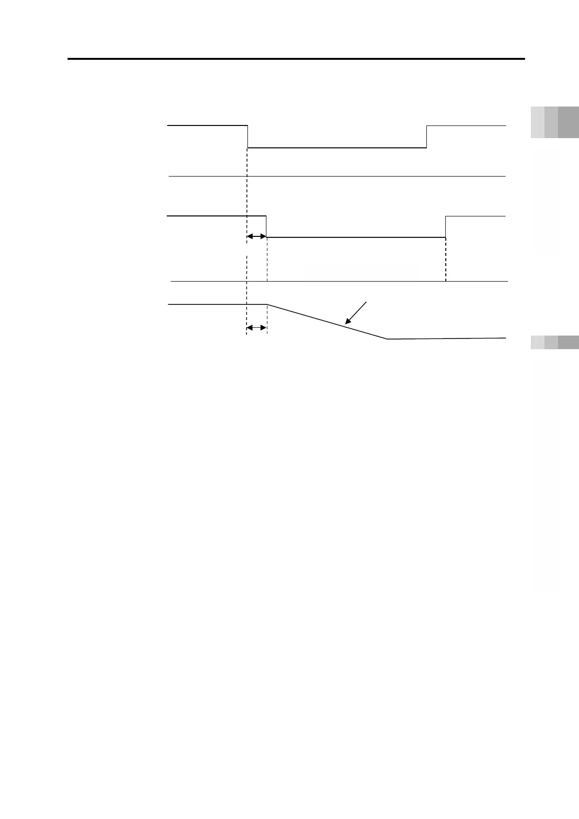
●Operation in malfunction
Operation in malfunction should be as shown in the diagram above when switches are
reduplicated as shown in the example of wiring.
When having one switch, the driver stop feature at malfunction should get invalid.
Internal Circuit Latency Time: * ms
( /SRI1)
( /SRI2)
Motor
Output Signal
(EDM)
Number of Motor Revolution
Reaction Time: 8ms or less