Note: Be sure to keep tension on the tape as the LBA is drawn into the cartridge by using a hex
wrench as shown in Figure 200 on page 266.
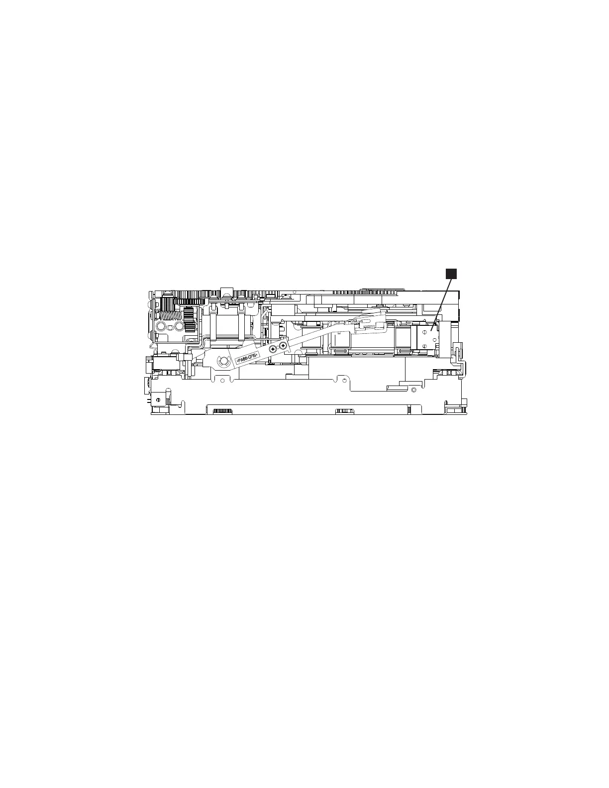
5. Notice the following mechanisms:
a. Loader mechanism gear (▌8▐) nearest the front of the drive that actuates the cartridge loader
mechanism
b. Position of the rotator stub (▌3▐).
c. Front loader motor worm gear (▌1▐). Rotating this gear allows the loader mechanism gear (▌8▐)
to turn.
6. Rotate the loader motor worm gear (▌1▐) to turn the loader mechanism gear (▌6▐) counterclockwise.
Continue turning until the rotator stub (▌3▐) loses contact with the lever (▌7▐). This action releases
the LBA leader pin.
7. Rotate the threader motor worm gear (▌4▐) to turn the threader mechanism gear (▌6▐)
counterclockwise. This action moves the LBA out of the cartridge and past the read/write head. Stop
this rotation when the LBA is near the tape guide roller nearest the rear of the drive (▌1▐).
8. Continue rotating the loader motor worm gear (▌1▐) until the rotate stub (▌3▐) is positioned as
shown. Notice that the rotator stub (▌3▐) is nearly aligned with the cartridge loader tray guide
bearing (▌2▐).
9. Remove the cartridge from the cartridge loader tray.
10. Go to “Ending procedure” on page 283.
Figure 203. Leader Block Assembly (LBA)
Appendix A. Information for trained service personnel 269

 Loading...


