6-50 ELECTRICAL SYSTEM / BILGE PUMP
ICON A5 / MAINTENANCE MANUAL CHANGE C2
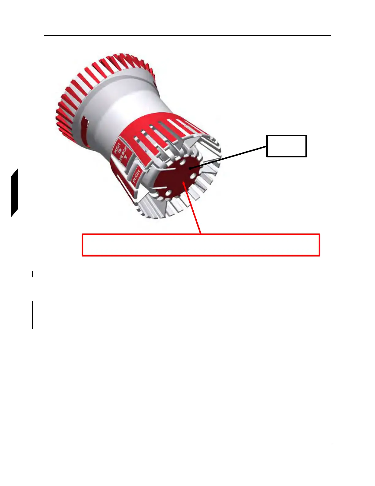
FIGURE 6-10
APPLY 3M FIRE BARRIER
3. Install the pump body onto the bottom strainer already in the aircraft by aligning it and rotating it
clockwise until locked.
4. Cut hose to 42.0”±1.0”, make cut in the center of the flat section. Attach the bilge pump hose to
the pump barb fitting and secure with a 3806 CLAMP as shown below. Route the hose as indi-
cated below. Slide one end of the hose onto the bulkhead fitting in the fuselage wall (until flush
with the fuselage wall) and the other end onto the bilge pump (until flush with the bilge pump).
The sealant squeeze out through the 3 holes and around the sides should
be wiped flush with top side surface of bonding flange.
Apply 3M
fire barrier