6-76 ELECTRICAL SYSTEM / FUEL LEVEL SENSOR
ICON A5 / MAINTENANCE MANUAL CHANGE C2
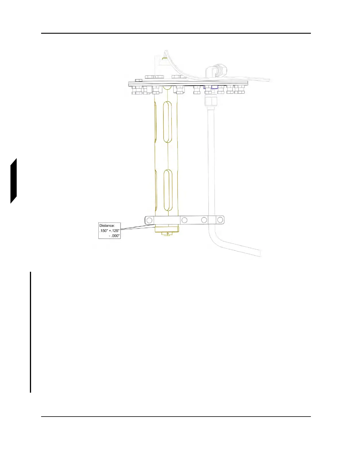
FIGURE 6-25
INSTALL CLAMP BRACKETS
11. Whenever the FUEL LEVEL SENSOR is replaced, also replace the FUEL TANK ACCESS PLATE
GASKET. Remove the original FUEL TANK ACCESS PLATE GASKET, clean the surface to make
sure there’s no sealant remaining on the fuel tank and the FUEL TANK ACCESS PANEL. Apply
sealant on both sides of the gasket as one continuous bead approximately .030”-.060” thick.
Sealant to be applied as straight lines between bolt holes and half crescents to the interior
around the bolt holes. Allow sealant to sit for 5 minutes after being applied to gasket surfaces
before placing gasket onto fuel tank.
12. Reinstall fuel level sensor and FUEL TANK ACCESS PLATE into the fuel tank with 12 AN3C4A
BOLT and washers. See Figure 6-22.
13. Connect EXTERIOR SUPPLY LINE and torque both ends to 110-130 in-lbs. See Figure 6-21.
14. Attach T9028 and T9026 ring terminals and install AN3C4A BOLT and washer into fuel level
sensor, apply LOCTITE 243. Torque to 40-45 in-lbs.
15. Connect the fuel level sensor connector to the aircraft harness. See Figure 6-21.
16. Verify continuity to ground between ring terminal and ground stud.