ELECTRICAL SYSTEM / FUEL LEVEL SENSOR 6-77
CHANGE C2 ICON A5 / MAINTENANCE MANUAL
17. Perform a fuel calibration test to ensure the fuel level indicating system and low-level switch are
operating correctly:
a. Sump fuel from the fuel tank, turn on aircraft to verify fuel low-level light come on.
b. Add three gallons of fuel into the fuel tank, verify the low-level light goes out.
c. Add two more gallons of fuel into the fuel tank and verify fuel level sensor reads about 5
gallons.
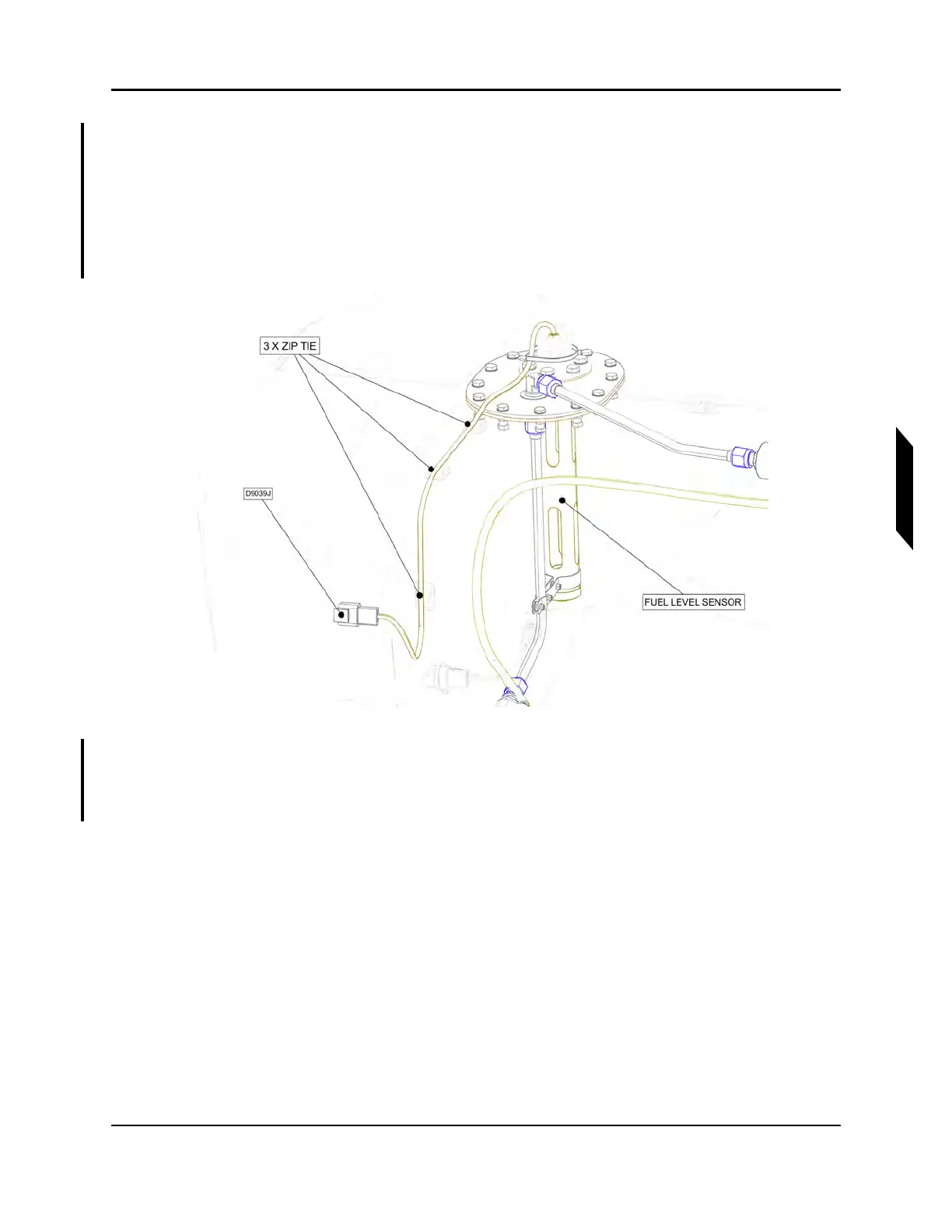
18. Secure fuel level sensor wire harness to zip tie mounts on fuel tank using three zip ties.
FIGURE 6-26
SECURE FUEL LEVEL SENSOR WIRE HARNESS
19. Apply LOCTITE 425 to OPTICAL SENSOR and install OPTICAL SENSOR into bottom of fuel
tank. Torque OPTICAL SENSOR to 12-15 in-lbs. Wrap connector with F4 tape. Secure wiring for
OPTICAL SENSOR to fuel tank using zip ties and cable tie mounts.