8-24 EQUIPMENT AND FURNISHINGS / EQUIPMENT AND FURNISHINGS GENERAL MAINTENANCE
ICON A5 / MAINTENANCE MANUAL CHANGE C1
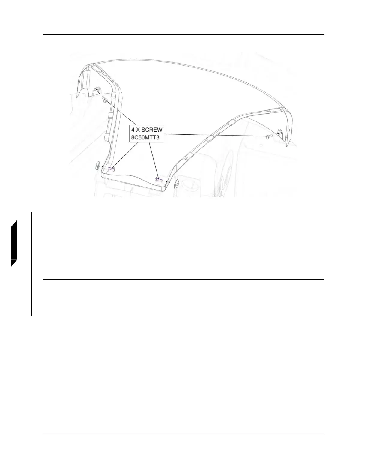
FIGURE 8-12
REMOVE CENTER SPINE SCREWS
5. Install center spine using four screws as shown in Figure 8-12, torque screws to 13 in-lbs.
6. Install Handhold using four screws as shown in Figure 8-11, torque screws to 13 in-lbs.
7. Install right instrument panel top panel. (See “Right Instrument Panel Top Panel Installation” on
page 8-18.)
8. Install left instrument panel top panel. (See “Left Instrument Panel Top Panel Installation” on page
8-21.)
VERIFICATION METHOD:
Task is complete when the center spine has been installed.