9-18 FLIGHT CONTROLS / ROLL CONTROLS
ICON A5 / MAINTENANCE MANUAL CHANGE C3
1. Ensure that the wings are in the extended and locked position.
2. Secure digital level to aileron surface with its long axis perpendicular to aileron hinge line.
3. Ensure that the adjacent flap trailing edge aligns flush with that of the inboard wing, then aileron
trailing edge to that of the flap and then set the Alt Ref function of the level with it in this position.
4. Check the LH and RH roll secondary stop:
a. Apply 15±2 lb at the center of the control stick grip. Force should be applied INBD and
OUTBD.
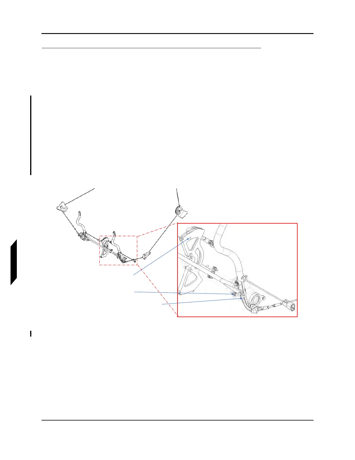
b. Verify that contact is made with the secondary roll stops (located at the base of the control
sticks as shown in Figure 9-13) at the specified force. If not within specified force adjust
the length of the secondary stop bolts using NAS1149C0363R washers. If a finer adjust-
ment is necessary it is permissible to use NSAS1149C0332R or NAS1149C0316R washers.
A minimum of three and maximum of seven NAS1149C0363R washers are allowed. Verify
proper thread protrusion of the bolt and nut of the secondary stop once complete.
c. Verifying that the primary roll stop (located in the wing) contracts prior to the RH secondary
stop at the control stick.
FIGURE 9-13
LOCATION OF SECONDARY ROLL STOP
5. Have a helper move the control stick to lower the aileron trailing edge down against the stop
(stop contact at outboard roll bellcrank should be heard). While holding very light (1-2 lb
f
) upward
FWD Pitch Sector Rig Pin Hole
Secondary Stop
Control Stick Rig Pin Hole