FLIGHT CONTROLS / ROLL CONTROLS 9-25
CHANGE C3 ICON A5 / MAINTENANCE MANUAL
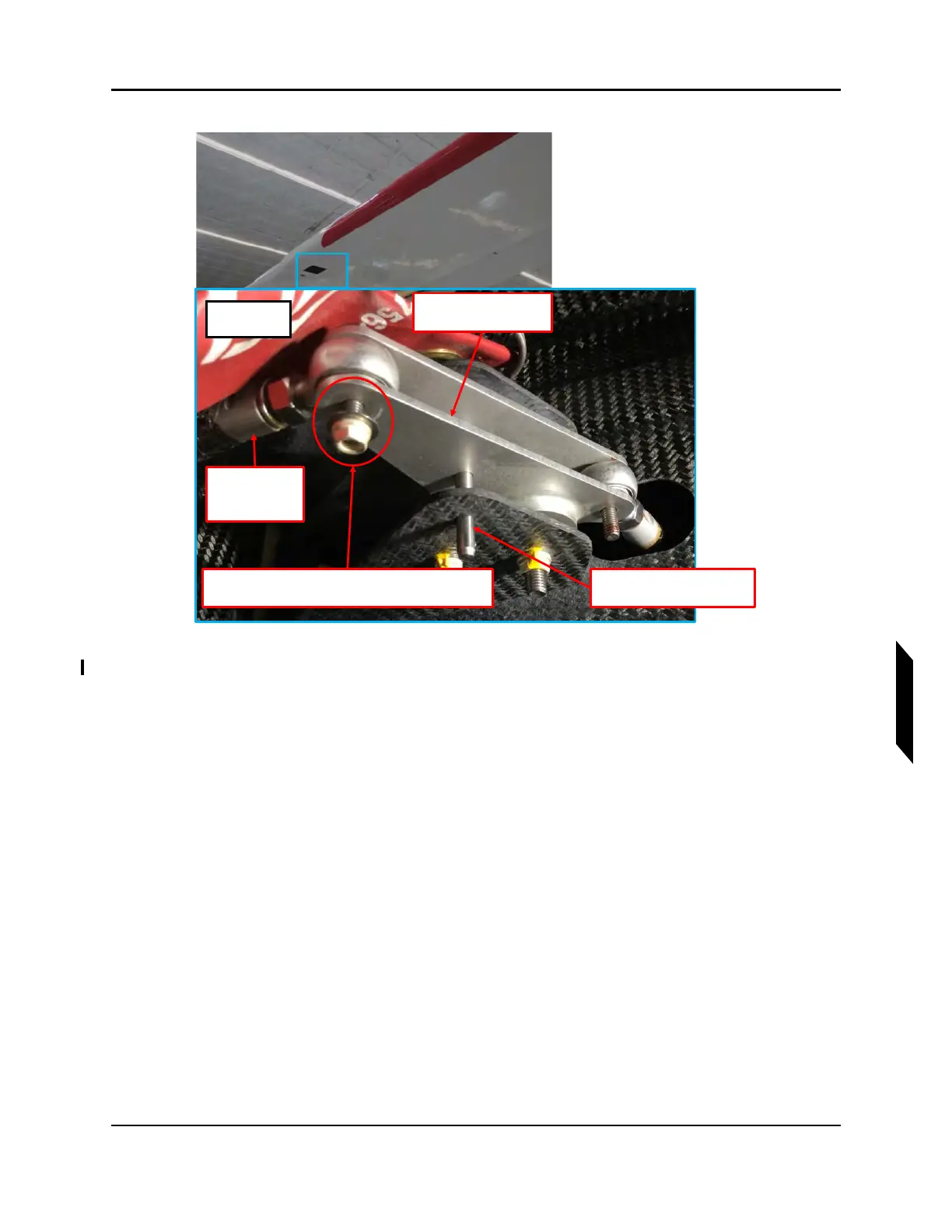
FIGURE 9-18
OUTBOARD ROLL BELLCRANK RIG PIN
14. Ensure flap has been rigged correctly. (See “Inspect Roll Rigging” on page 9-17.)
15. Adjust outboard push tube rod ends equally to align aileron trailing edge with flap trailing edge
within 0+/-.02 in. Once adjusted, torque push tube jam nut to 60 in-lbs. Torque through bolt and
locking nut to 20 in-lbs.
16. Secure a digital protractor to the top surface of the aileron using double sided tape or equivalent.
Set the protractor to zero. See Figure 9-19.
REMOVE THIS HARDWARE TO ADJUST THIS ROD
END TO LINE UP RIG PIN HOLES
RIG PIN INSTALLED
THROUGH BELLCRANK
INBOARD
AILERON PUSH
TUBE
OUTBOARD ROLL
BELLCRANK
LH SHOWN
RH OPPOSITE