9-24 FLIGHT CONTROLS / ROLL CONTROLS
ICON A5 / MAINTENANCE MANUAL CHANGE C3
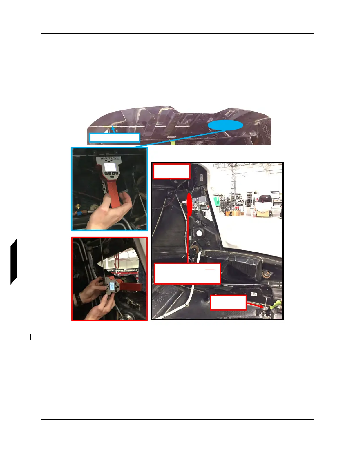
10. Use a tensiometer (upper cable thickness = 3/32 in, LH and RH fuselage cable thickness = 1/8
in) to rig the pilot side fuselage control cable, the copilot side fuselage control cable, and the
upper control cable. Achieve the following, refer to Figure 9-17:
a. Adjust turnbuckles to set cable tension on all 3 cables to 25-30 lbs.
b. After tensions are set on all 3 cables, ensure that only 3 threads or less are exposed on all
cable terminal sides and only 12 threads or less are exposed on all rod end sides. Re-rig
and adjust as necessary.
FIGURE 9-17
TENSIOMETER AND CABLE ADJUSTMENT LOCATIONS
11. Install turnbuckle clips into turnbuckles connecting control cables to control sticks. ICA012104
clip goes on the rod end side and the MS21256-1 clip goes on the control cable side.
12. With rig pins installed, unfold and lock both aircraft wings.
13. Install 2X .1875 in diameter rig pins through the outboard roll bellcranks. If the pin will not install,
adjust length of inboard aileron push tube by adjusting rod end lengths as necessary to align the
holes in the bracket and bellcrank. Adjust rod end lengths equally. Once adjusted, torque push
tube jam nut to 60 inlbs. Torque through bolt and locking nut to 20 inlbs. See Figure 9-18.
SET TENSIOMETER FOR 1/8”
CABLE THICKNESS AND
LOCATE TENSIOMETER HERE
ADJUST
TURNBUCKLE
LH SHOWN
RH OPPOSITE
ADJUST TURNBUCKLE