9-50 FLIGHT CONTROLS / PITCH CONTROLS
ICON A5 / MAINTENANCE MANUAL CHANGE C3
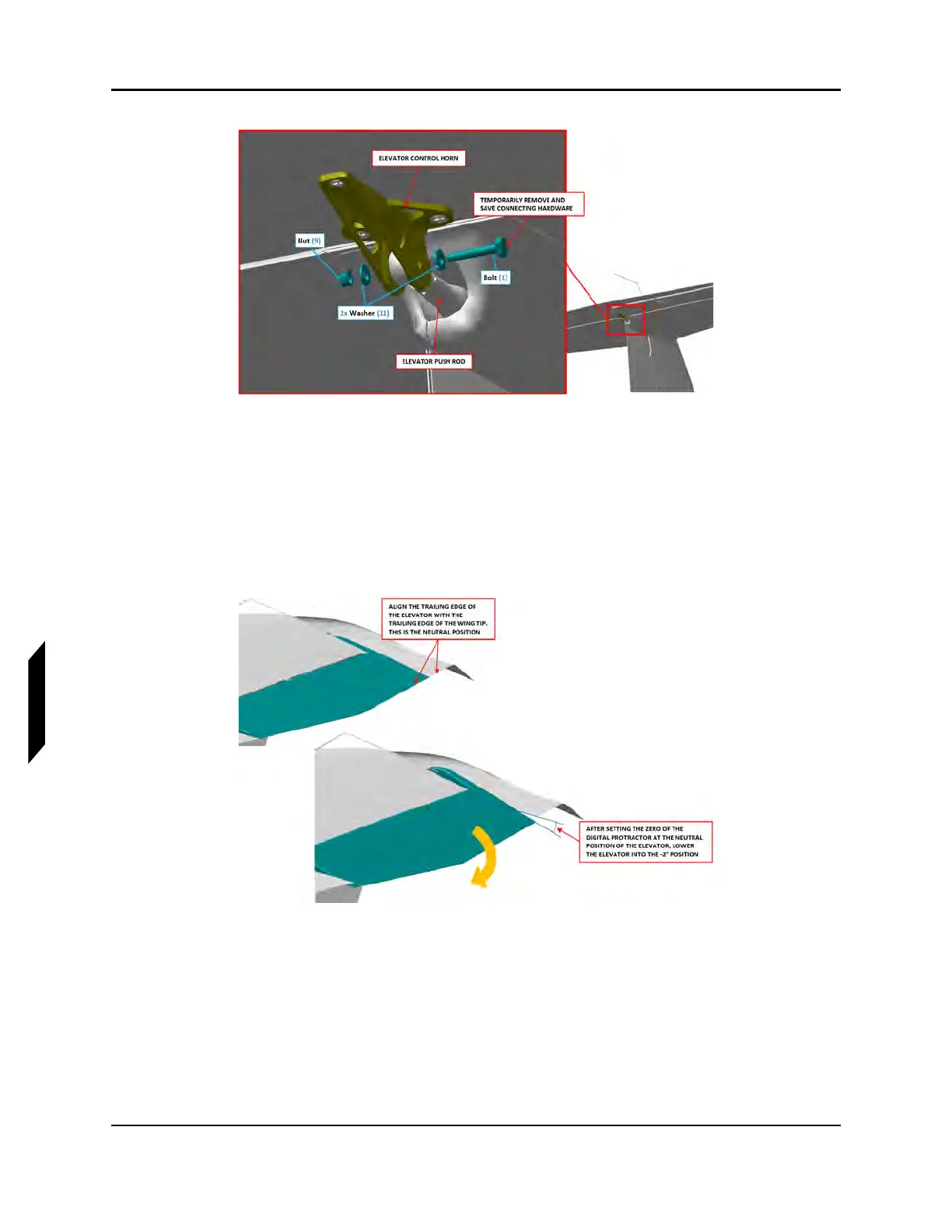
FIGURE 9-36
CONTROL HORN HARDWARE INSTALLATION
17. Place the digital protractor on top of the elevator and zero the digital protractor while the
elevator is in its neutral position, the trailing edge of the elevator should align with the HT tips.
18. After setting the zero position of the elevator, lower the elevator into the -2° position.
19. Adjust the rod end as necessary so that the rod end lines up with the elevator control horn while
the elevator is in the -2° position. This will be the initial adjustment. If necessary, final adjustments
will be made at a later step if required. See Figure 9-37.
FIGURE 9-37
ELEVATOR RIGGING
20. Temporarily install the hardware which secures the elevator push rod to the elevator control
horn. See Figure 9-36.
21. Using the digital protractor, check the maximum upward and downward deflection of the
elevator. If required, adjust the elevator push tube rod end as necessary to achieve the following:
a. 19° ± 1° upward deflection
b. 21° ± 2° downward deflection