FUEL SYSTEM / FUEL TANK (MY18+) 10-21
CHANGE C2 ICON A5 / MAINTENANCE MANUAL
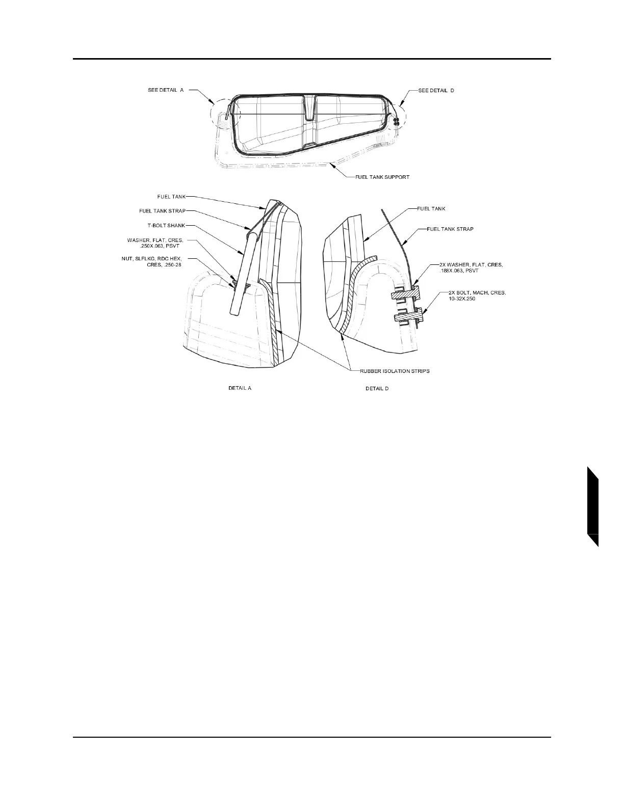
FIGURE 10-6
FUEL TANK STRAP INSTALLATION
2. Install the fuel tank subassembly into the aircraft fuel tank support structure.
3. Attach the fuel tank strap subassemblies to AFT end of fuel tank support brackets using LUBRI-
CANT and hardware. (See Figure 10-6. Detail D.) Torque bolts to 26 in-lb.
4. Loosely secure the forward ends of the fuel tank straps to the fuel tank brackets using LUBRI-
CANT and hardware. (See Figure 10-6. Detail A.)
5. Adjust isolation channels on the fuel tank straps to ensure that the fuel tank strap will not contact
the fuel tank surface after the straps are tensioned. Torque nuts to 10-13 in-lb.
6. Route fuel sump hose through bottom end of fuel filler neck and connect the fuel sump hose to
sump hose adapter using a new CLAMP, HOSE, CRIMP (Oetiker clamp). Tighten with ear-clamp
crimpers. (See Figure 10-7.)