14-6 LANDING GEAR / TROUBLESHOOTING
ICON A5 / MAINTENANCE MANUAL CHANGE C2
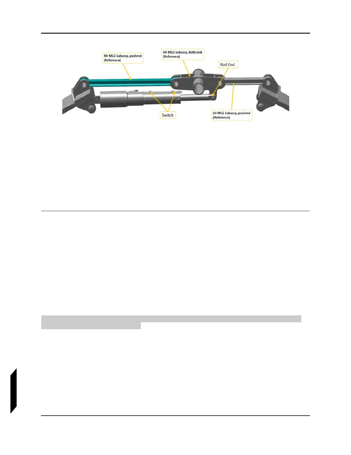
FIGURE 14-1
MAIN LANDING GEAR INSTALLATION
5. Move the digital protractor to the Bellcrank surface and read measurement.
STEP RESULT: The measurement on the protractor should read 3.822 ± .237°.
6. Verify that the nose gear bellcrank and drag link are in line with one another in the extended posi-
tion.
7. Turn on master switch and verify that in the cockpit the landing gear indicator is in the landing
gear down position.
VERIFICATION METHOD:
Check that the results are within the acceptable limits.
RELATED INFORMATION:
"Removal and Installation of Inspection Panels and Fairings" on page 3-34
"Empty Weight and CG Measurement While on Jackpoint Scales" on page 3-32
"Condition and 100-Hour Inspection—Landing Gear" on page 3-14
14.3.2 Check Landing Gear Retracted Position
The following section contains the information required to evaluate the rigging of the landing gear
components in the retracted position.
TASK INFORMATION:
Type of Maintenance
Line
Level of Certification
LSA-RM
Task Specific Training Required
No