14-14 LANDING GEAR / TROUBLESHOOTING
ICON A5 / MAINTENANCE MANUAL CHANGE C2
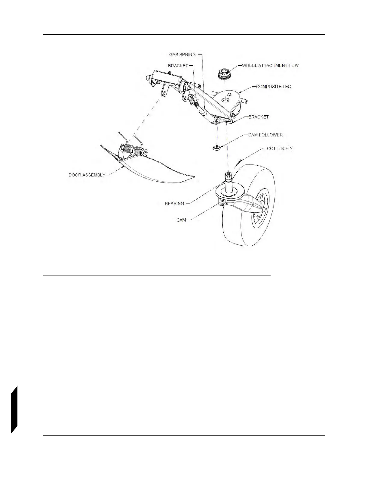
FIGURE 14-4
NOSE WHEEL CENTERING.
1. Inspect cam face, as well as the cam follower face for scaring, pitting, grooving or any visible
damage.
STEP RESULT: Both faces should be completely smooth and should be free of all described defects.
2. Verify security of both brackets depicted in illustration.
3. Confirm that all attachment hardware is securely in place, special attention should be given to
the cotter pin used to prevent un-threading of the wheel attachment hardware. Refer to illustra-
tion.
4. Inspect the proper function of the wheel rotation bearing (Figure 14-4) coupled with cam mech-
anism.
a. Turn the aircraft 60 degrees.
b. Lift the nose by hand by firmly grasping the bow ring to ensure proper centering of the nose
wheel.
VERIFICATION METHOD:
Check is successful if hardware is in good condition and nose wheel rotates to center when lifted off
of the ground.