14-34 LANDING GEAR / BRAKE LINE
ICON A5 / MAINTENANCE MANUAL CHANGE C2
14.5.1.3.2 Parking Brake Valve Assembly and Installation Procedure
Use the following procedure to assemble and install the parking brake valve.
TASK INFORMATION:
Type of Maintenance
Line
Level of Certification
LSA-RM
Task Specific Training Required
No
Special Tools Required
None
Parts Required
None
Aircraft System and Number
11—Landing Gear
Consumables
Tef-Gel
®
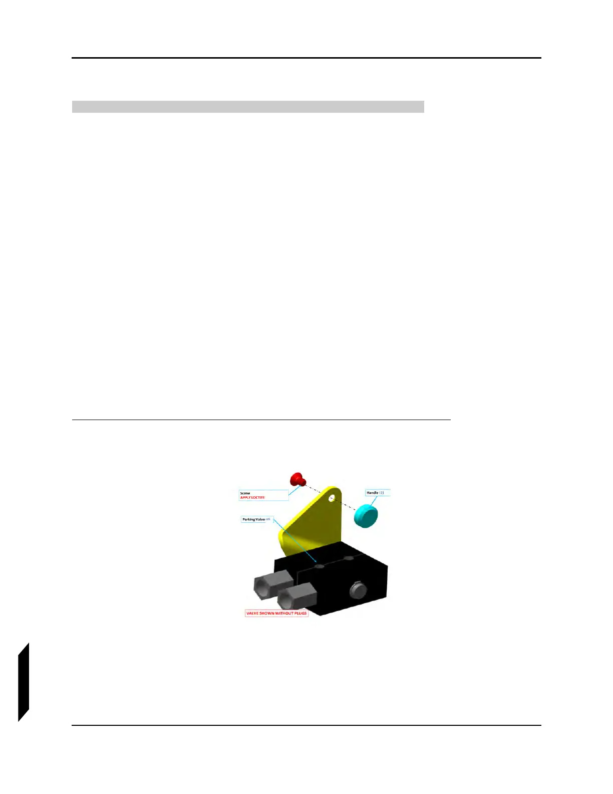
1. Install parking brake handle on the parking valve using the screw indicated. Apply thread locker
to leading screw threads.
FIGURE 14-17
INITIAL ASSEMBLY OF PARKING VALVE
2. Torque screw to 13 in-lb.
3. Remove the plugs from parking valve.
4. Apply a 360° bead of threadlocker to the leading threads of the NPT thread end of the fittings.
Install fittings into valve until finger tight.