LANDING GEAR / BRAKE LINE 14-35
CHANGE C2 ICON A5 / MAINTENANCE MANUAL
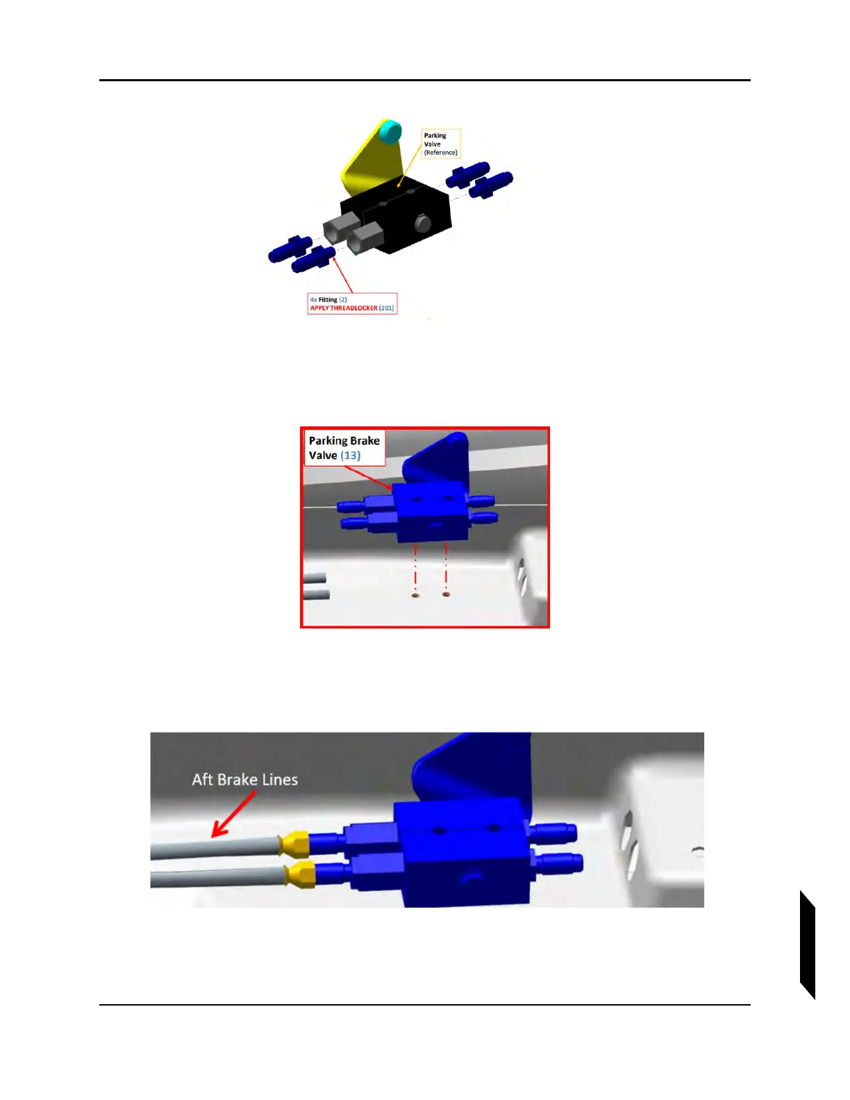
FIGURE 14-18
FINAL ASSEMBLY OF PARKING VALVE
5. Wrench tighten 2-3 full turns from finger tight. DO NOT EXCEED 100 in-lb.
6. Place parking brake valve in its installation location as shown (but do not install bolts).
FIGURE 14-19
ORIENTATING THE PARKING VALVE
7. Connect AFT brake lines to parking brake valve. Torque fittings to 90-132 in-lb. Check that hard-
ware is secure.
FIGURE 14-20
INSTALLATION OF BRAKE LINES ONTO PARKING VALVE
8. Connect brake line fittings to parking brake valve and lower adapters on brake master cylinders.