LANDING GEAR / MAIN LANDING GEAR 14-49
CHANGE C2 ICON A5 / MAINTENANCE MANUAL
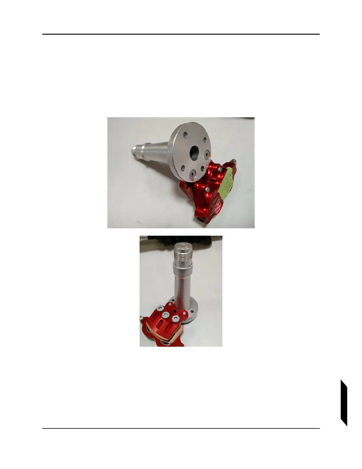
2. Reattach axle to the landing gear leg using the retained hardware and reinforcement plate.
Orient plate so that the rounded edge faces inboard.Coat the bolts with a thin layer of Tef-Gel
®
on installation, torque to 60 in-lb.
3. Reinsert brake rotor into caliper with the printed side of the rotor facing inboard.
4. Coat the entire axle with a thin layer of MOLYKOTE™ grease.
5. Slide spacer over the axle and reattach wheel. Ensure that the teeth on the brake rotor sit
completely within the grooves of the wheel assembly. Apply MOLYKOTE™ grease to the axle
threads and tighten wheel nut to 216 in-lb per the Beringer Manual.
FIGURE 14-24
WHEEL AXLE DETAIL.
6. Install a cotter pin through the axle and reinsert wheel seal cap.