LANDING GEAR / NOSE LANDING GEAR 14-75
CHANGE C2 ICON A5 / MAINTENANCE MANUAL
Special Tools Required
ITL001714 (Nose Landing Gear Rigging Tool)
Parts Required
ICA013071 (NLG Actuator)
Aircraft System and Number
11—Landing Gear
Consumables
Tef-Gel
®
1. Slide NLG Actuator into the NLG box and attached the aft end of the actuator to the NLG box
bracket using the AN4C10A bolt, NAS1149C0432R washer, MS21032-4 nut, ICA008136 bushing
as shown in the graphic below. Torque bolt to 48 in-lb
f
.
2. Slide NLG Actuator boot (119255) over the NLG actuator rod end and secure with large clamp
(30-45/9-W5) and small clamp (3808) as shown in the graphic below. Torque clamps until there
is a rise in torque then 1/4 turn additional. Allow approximately .125” of the rod end extension
beyond the boot. Allow approximately .05” of boot to protrude beyond the clamp.
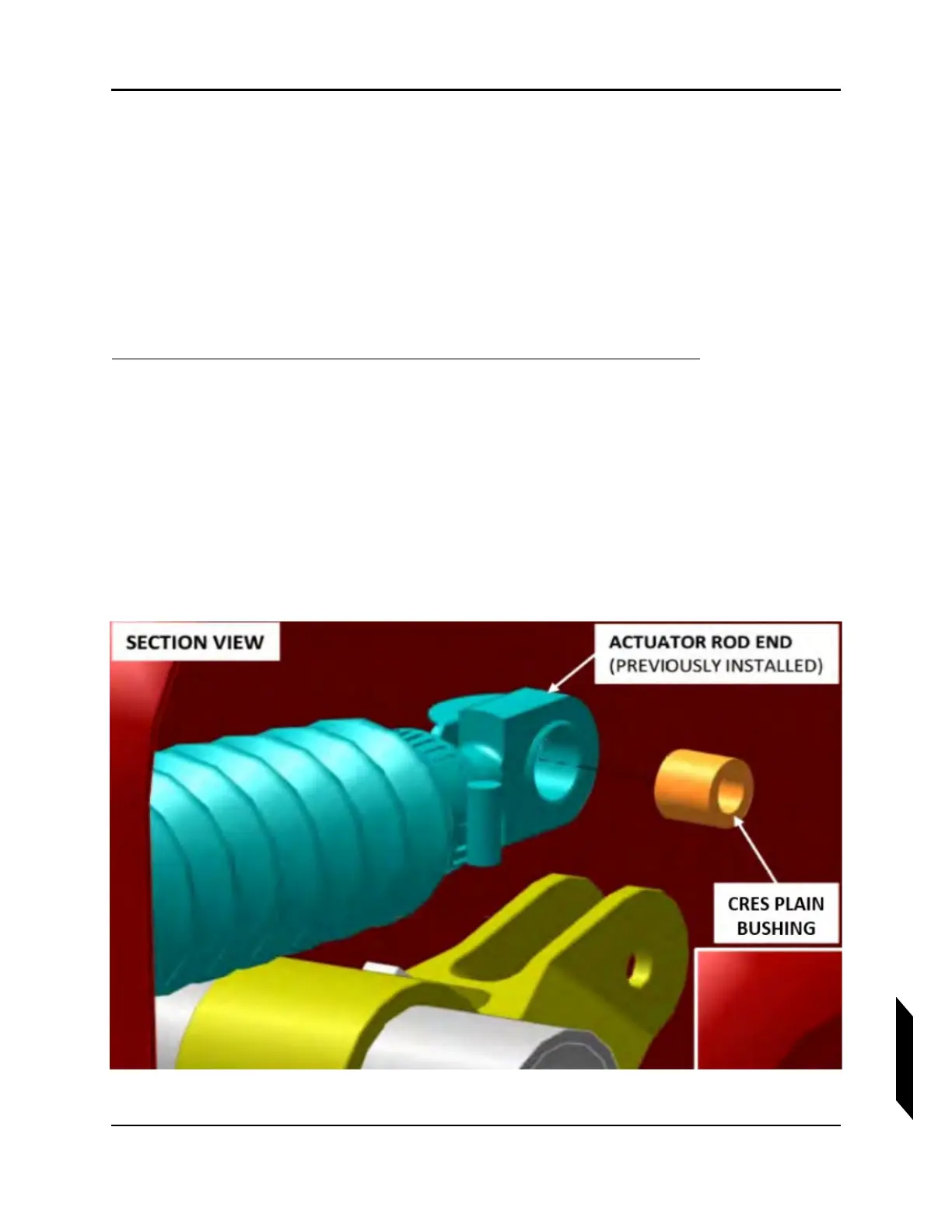
3. Insert CRES Plain Bushing and connect the rod end to the NLG bell crank using the bolt
(AN4C10A) and washer (under bolt head) (NAS1149C0432R) as shown in the two graphics
below. Apply Tef-Gel
®
to bushing and bolt threads and shank prior to assembly. Torque bolt to
54 in-lb
f
.
FIGURE 14-28
ACTUATOR DETAILED VIEW