14-76 LANDING GEAR / NOSE LANDING GEAR
ICON A5 / MAINTENANCE MANUAL CHANGE C2
4. Electrically connect NLG actuator to the aircraft wiring harness by connecting to D9024P of the
FWD Fuselage Wire Harness.
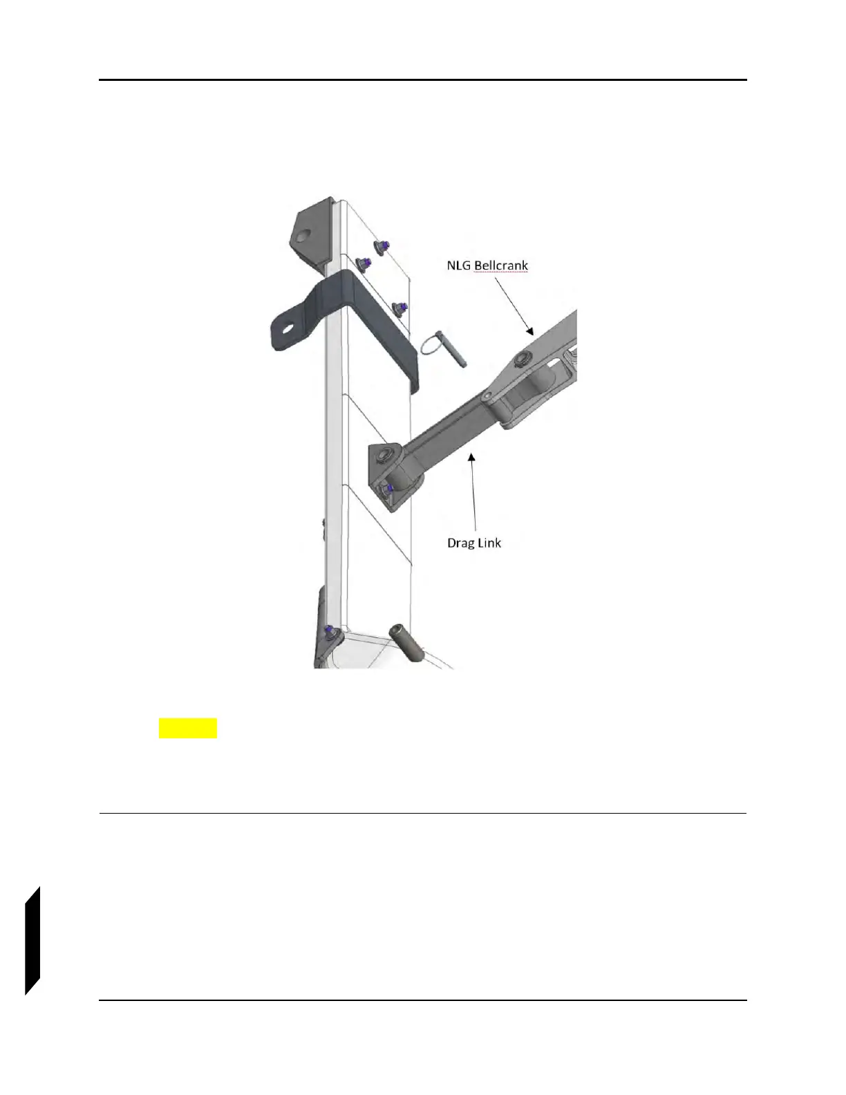
5. Rig the stops on the NLG actuator extended travel such that the Tooling Pin fits flat (with no
gaps) against both the NLG Bell Crank and NLG Drag Link as graphically shown below.
FIGURE 14-29
NLG TOOLING PIN
CAUTION: Special care should be given to make sure this forward rig is set
correctly.
6. Rig the NLG Actuator retract travel such that force required to pull the NLG off the stop at the
top of the NLG box is 3-4 lbs measured at the wheel axle.
VERIFICATION METHOD:
Jack up aircraft and swing both main and nose gear together 10 times. Perform return to service flight.