PROPULSION / ENGINE 16-23
CHANGE C2 ICON A5 / MAINTENANCE MANUAL
3. Clear the engine bay and firewall area of tools and debris and inspect the area to ensure that the
engine may be installed.
4. Inspect and clean the threads of engine mount bolts and coat their shank and threads with
LUBRICANT.
5. Clean the nutplates in the main wing spar (forward engine mount bolt locations) and apply LUBRI-
CANT to their threads.
6. Install the ITL-902 Engine Hoist End Effector on the engine per the tool’s instructions.
NOTE: Do not use the fuel line assembly to lift the engine.
7. Lift the engine using a properly rated engine hoist and position the engine over the engine bay.
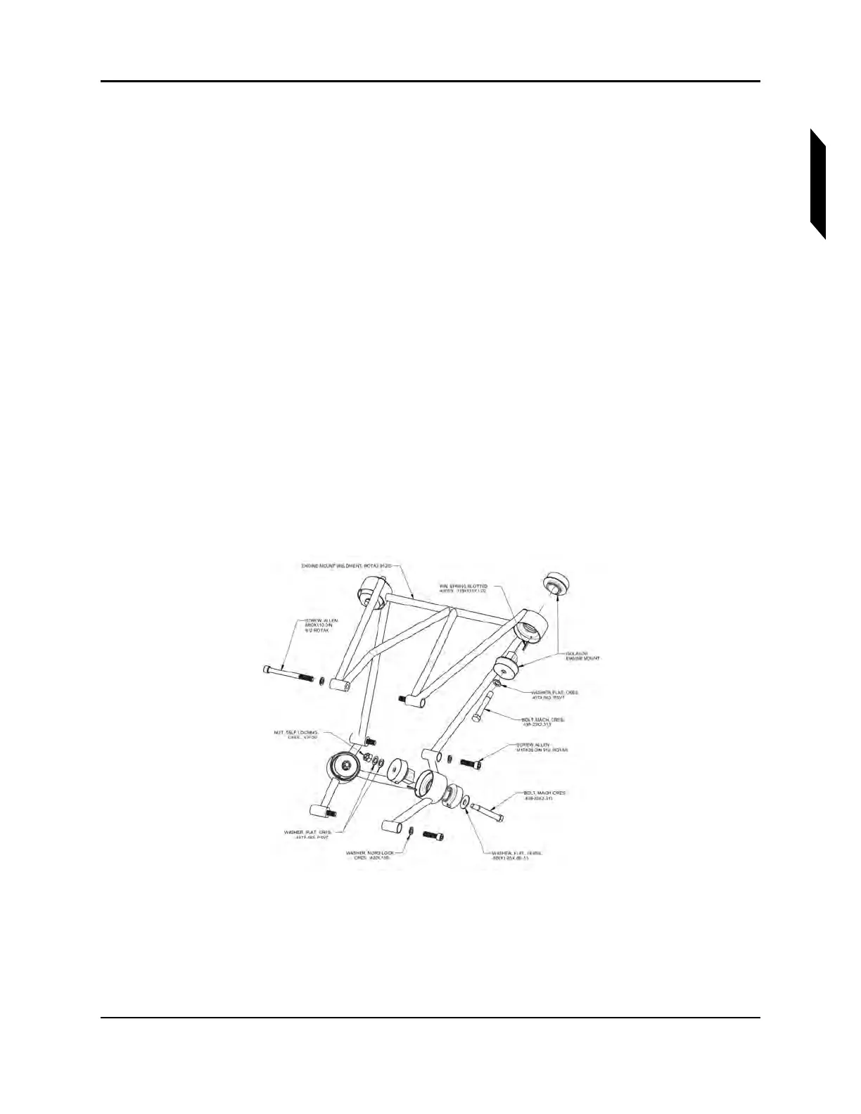
8. Install the four sets of 94150-40 engine mount isolators, being careful that the roll pins in the
mount weldment engage the alignment holes in the isolators. If isolators fit loosely, use tape to
temporarily hold them in place.
9. While lowering the engine into position, guide the engine harnesses along the correct path
through and around the engine mount and then through the appropriate firewall pass-throughs.
10. Align the engine mount with the mounting holes in the firewall and remove any tape from isola-
tors.
11. Loosely attach the engine at the aft two mounting points. (See Figure 16-11.) Install each bolt up
from inside the fuselage with one washer under the head and with a self-locking nut with two
washers under it. Do not tighten these fasteners yet.
12. Install the two forward engine mount bolts with one washer under each head. Do not tighten
these fasteners yet.
FIGURE 16-11
RETURN LINE FITTING AND FIREWALL CLEARANCE
13. Ensure that there is a clearance of approximately 3/8” between the firewall and engine oil return
fitting using a 3/8” spacer. (See Figure 16-12.) If the clearance is less, lightly loosen the fitting and
use a 7/8” 12-point crows foot wrench to torque the fitting. (See Figure 16-13.)
14. Remove the spacer.