PROPULSION / ENGINE 16-89
CHANGE C2 ICON A5 / MAINTENANCE MANUAL
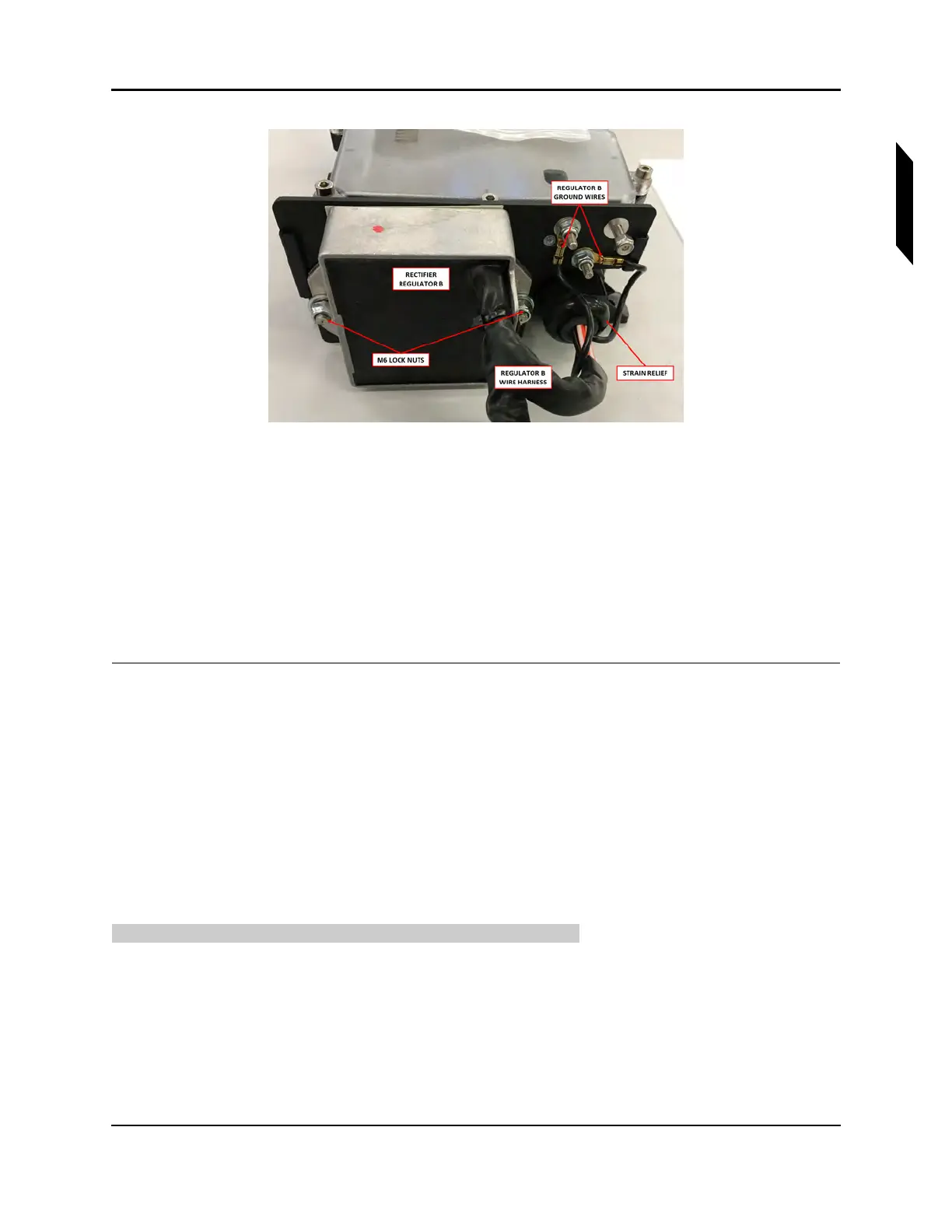
FIGURE 16-56
REGULATOR B SIDE OF FUSE BOX
8. Remove two M6 lock nuts (12) and washers (13) to remove the regulator from the fuse box.
9. Remove nine M4x16 Allen screws (10) and plastic washers (11) to remove the fuse box cover.
10. Loosen the strain relief (8,9).
11. Remove the ring terminals inside the fuse box. Remove a M5 lock nut (15), M4 lock nuts (16), and
washers (14,17).
12. Feed the regulator wiring out of the strain relief.
13. If required, repeat Steps 7-12 to remove the second regulator.
VERIFICATION METHOD:
The task is completed when the fuse box and regulators have been removed.
RELATED INFORMATION:
"Removal and Installation of Inspection Panels and Fairings" on page 3-34
"Inspect Regulator Wires" on page 16-84
16.1.9.4.2 Install Fuse Box and Regulators
Use the following task to install the fuse box and both regulators.
TASK INFORMATION:
Type of Maintenance
Line
Level of Certification
LSA-RM