16-88 PROPULSION / ENGINE
ICON A5 / MAINTENANCE MANUAL CHANGE C2
4. Disconnect Regulator A (black) and Regulator B (gray) connectors.
5. Remove the ring terminals from the ground studs on both sides of the fuse box.
• Terminals T9077, T9079, and T9081 from fuselage wire harness
• All ring terminals from ROTAX wire harness
6. Remove four 8-32 x 0.375 screws and washers to remove fuse box. Retain hardware for
re-installation.
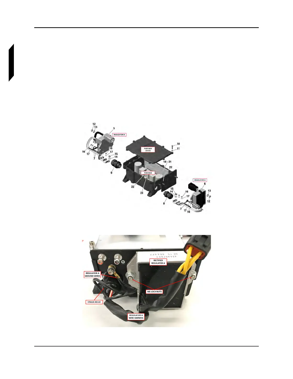
7. Remove the ground terminals from the ground studs. Retain hardware for re-installation. Fuse
box components are labeled by number. See Figure 16-54.
• For Regulator A, Remove one M4 lock nut (16) and washer (17) to remove two black ground
wires (7) on one ground stud. See Figure 16-55.
• For Regulator B, remove two black ground wires (7). See Figure 16-56.
FIGURE 16-54
FUSE BOX EXPLODED VIEW
FIGURE 16-55
REGULATOR A SIDE OF FUSE BOX