PROPULSION / ENGINE 16-91
CHANGE C2 ICON A5 / MAINTENANCE MANUAL
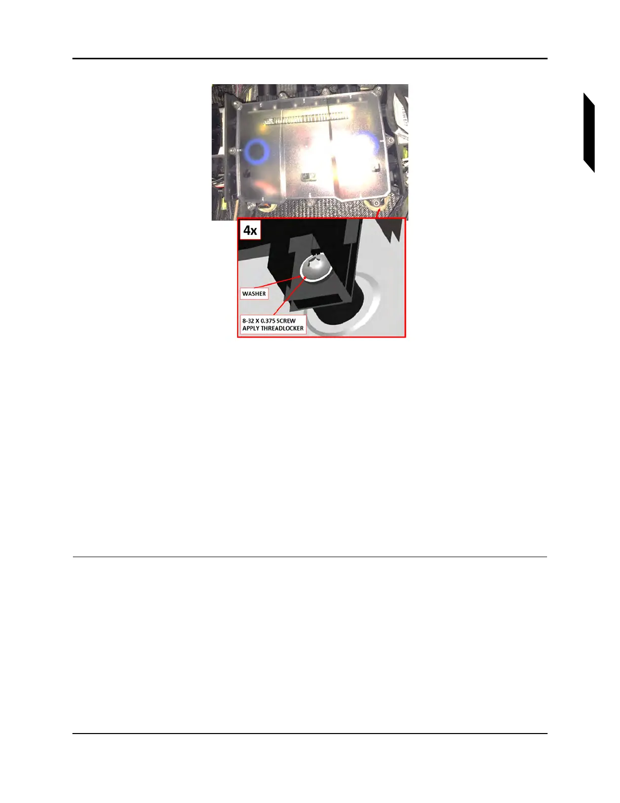
FIGURE 16-57
CLOSE-UP VIEW OF FUSE BOX MOUNTING SCREWS
9. Ensure O-rings are installed and connect the three cannon connectors. See Figure 16-52.
• Connector D9069P from fuselage wire harness
• Connector D9106P from engine LANE B extension wire harness
• Connector D9104P from engine LANE A extension wire harness
10. Secure the ring terminals to the ground studs with M4 nuts and washers. Do not install more than
five rings on any single ground stud. See Figure 16-53.
• Terminals T9077, T9079, and T9081 from fuselage wire harness
• All ring terminals from ROTAX wire harness
11. Connect Regulator A (black) and Regulator B (gray) connectors.
12. Install the AFT bulkhead baggage panel. (See “Removal and Installation of Inspection Panels and
Fairings” on page 3-34.)
VERIFICATION METHOD:
Complete the engine test run. (See “Engine Test Run” on page 16-7.)
RELATED INFORMATION:
"Engine Test Run" on page 16-7
"Removal and Installation of Inspection Panels and Fairings" on page 3-34