PROPULSION / PROPELLER 16-99
CHANGE C2 ICON A5 / MAINTENANCE MANUAL
6. Run the optical tachometer and accelerometer wire together to the front of the aircraft. Secure
with SpeedTape. (See Figure 16-60.)
7. Connect both sensors to the Propeller Balancer System unit.
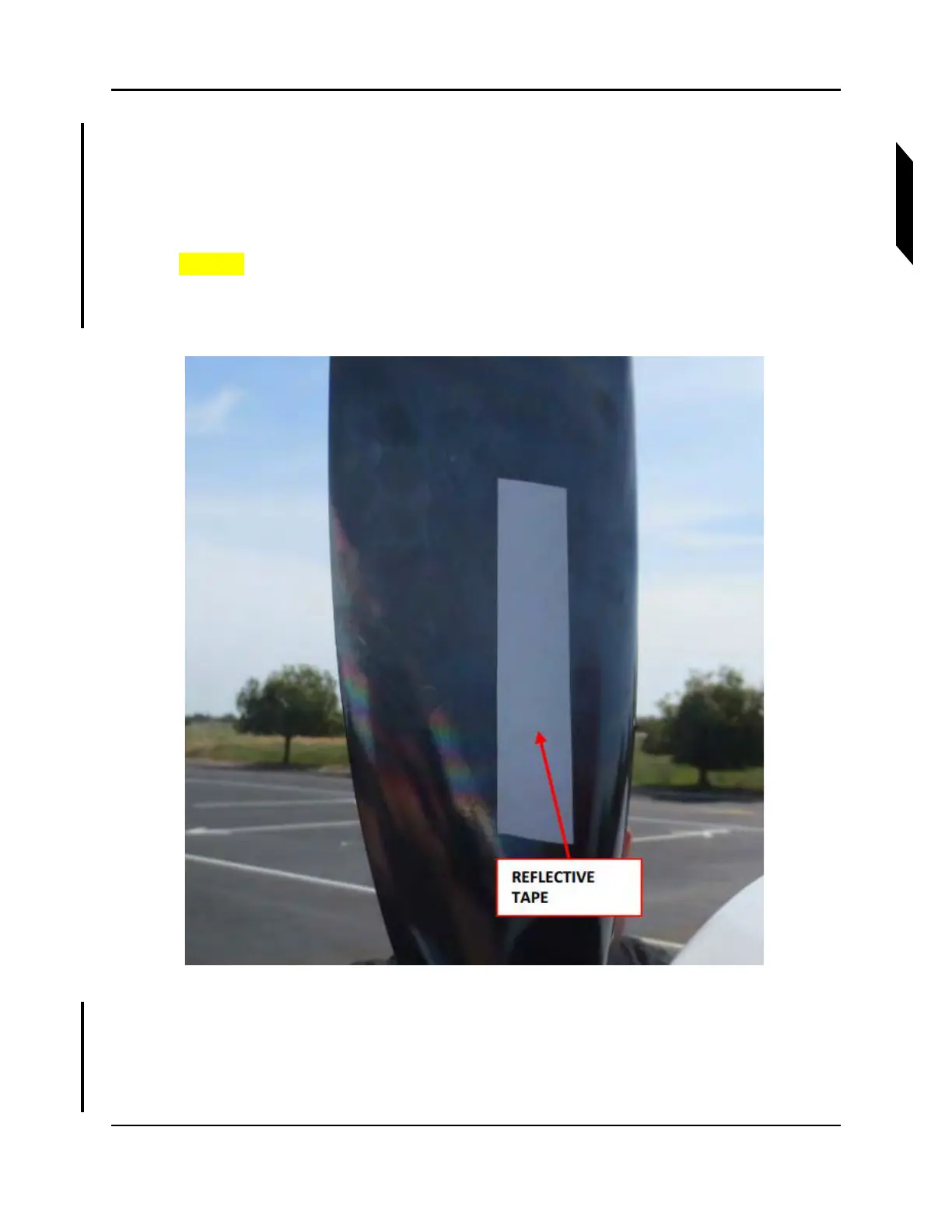
8. Place TAPE, REFLECTIVE on one of the propeller blades on the FWD face of the blade. The tape
must be in the line of sight of the photo tachometer. This blade is now identified as Blade 1. (See
Figure 16-62.)
CAUTION: Turn propeller only counterclockwise looking FWD.
NOTE: Use a ruler to ensure the reflective tape is within the line of sight of
the sensor.
FIGURE 16-62
EXAMPLE OF REFLECTIVE TAPE PLACEMENT
9. Perform propeller balance using selected Propeller Balance System and its manual. After the
system runs the test, it will output a vibration magnitude in inches per second (IPS) and suggest
locations for adding weight.
NOTE: Engine speed should be 5000-5100 RPM during balancing.