16-100 PROPULSION / PROPELLER
ICON A5 / MAINTENANCE MANUAL CHANGE C2
10. Rotate the propeller until the reflective tape is aligned with the photo tachometer.
11. AFT looking forward, raise the propeller protractor centered over the spinner. Align the sensor
icon with the vibration sensor.
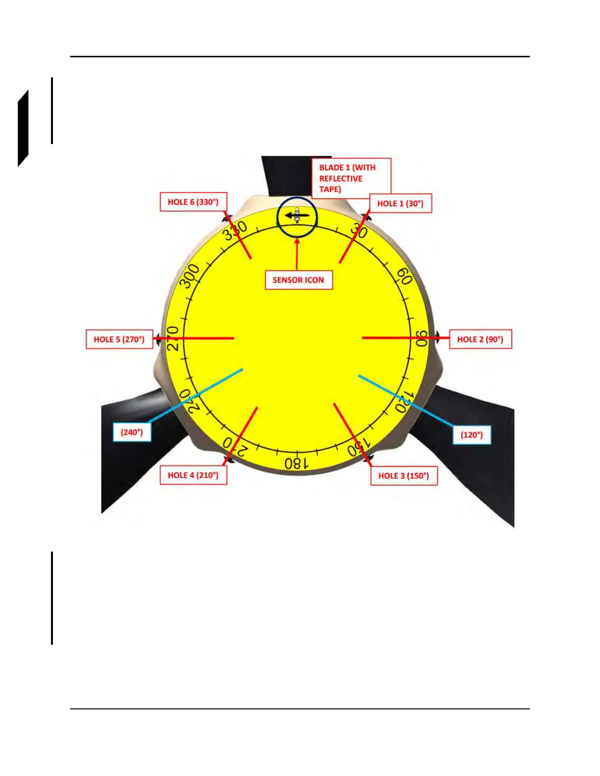
12. Use the protractor and Figure 16-63 to select one of the six holes that best matches the
suggested location for installing washers.
FIGURE 16-63
EXAMPLE OF PROPELLER PROTRACTOR ALIGNMENT AFT LOOKING FWD
13. Install a combination of washers listed in this task to achieve the suggested weight calculated by
the system. No more than three washers should be added to any one location. Apply LUBRICANT
to spinner dome screws and torque to 26 in-lbs with a T20 Torx driver. (See Figure 16-64.)
NOTE: The original screws may be replaced with longer screws, but the
additional weight must be accounted for. Ensure there are at least
two threads protruding out of the nut plate.