WING / WING LOCK 17-25
CHANGE C2 ICON A5 / MAINTENANCE MANUAL
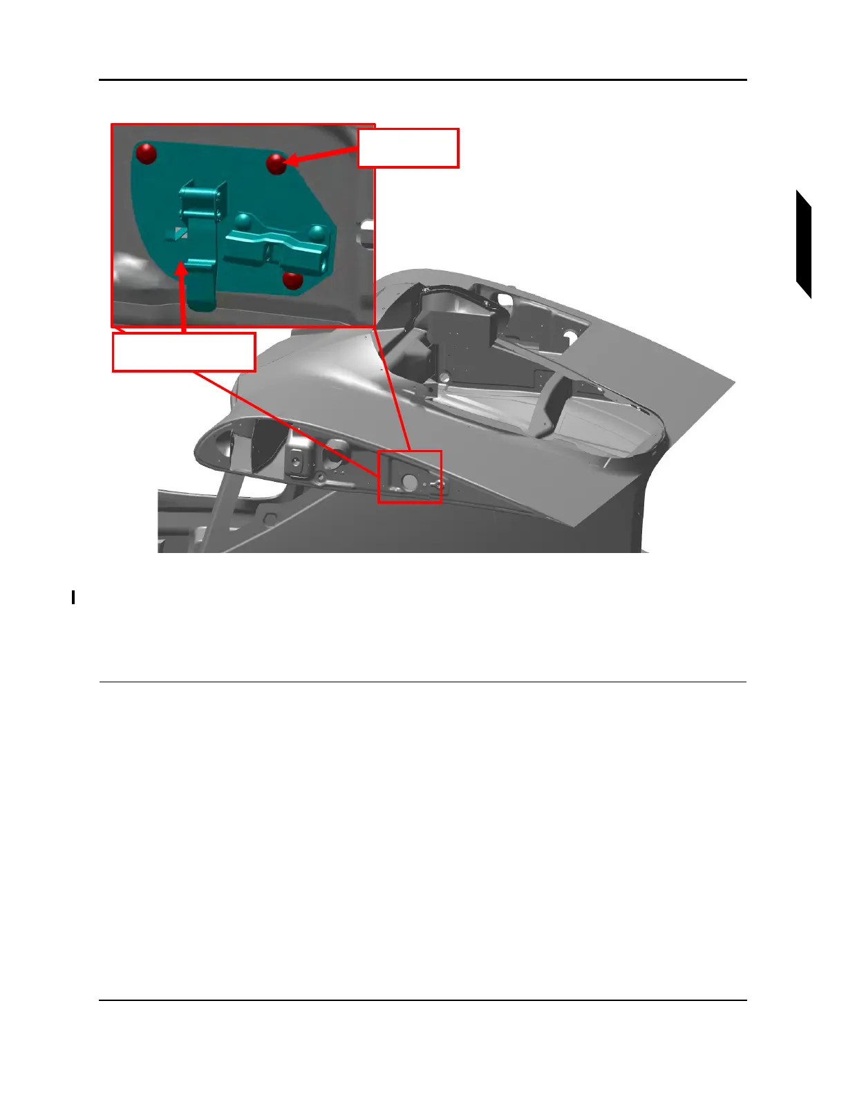
FIGURE 17-4
REMOVE WING LOCK SWITCH PLATE
2. Use a T15 Torx drive to remove the three 8-32 truss-head screws attaching the wing lock switch
plate assembly to the fuselage BL38 Rib. See Figure 17-4.
3. Pull the plate assembly out of the BL38 Rib and disconnect it from the aircraft electrical harness
VERIFICATION METHOD:
The procedure is complete when the wing lock switch mounting plate has been removed.
3x Screws
Lubricant
LH Lock Mechanism
Assembly