ICON PARACHUTE SYSTEM (IPS) / HARNESS 19-19
CHANGE C1 ICON A5 / MAINTENANCE MANUAL
FIGURE 19-12
FORWARD STARBOARD HARNESS MOUNT LOCATIONS
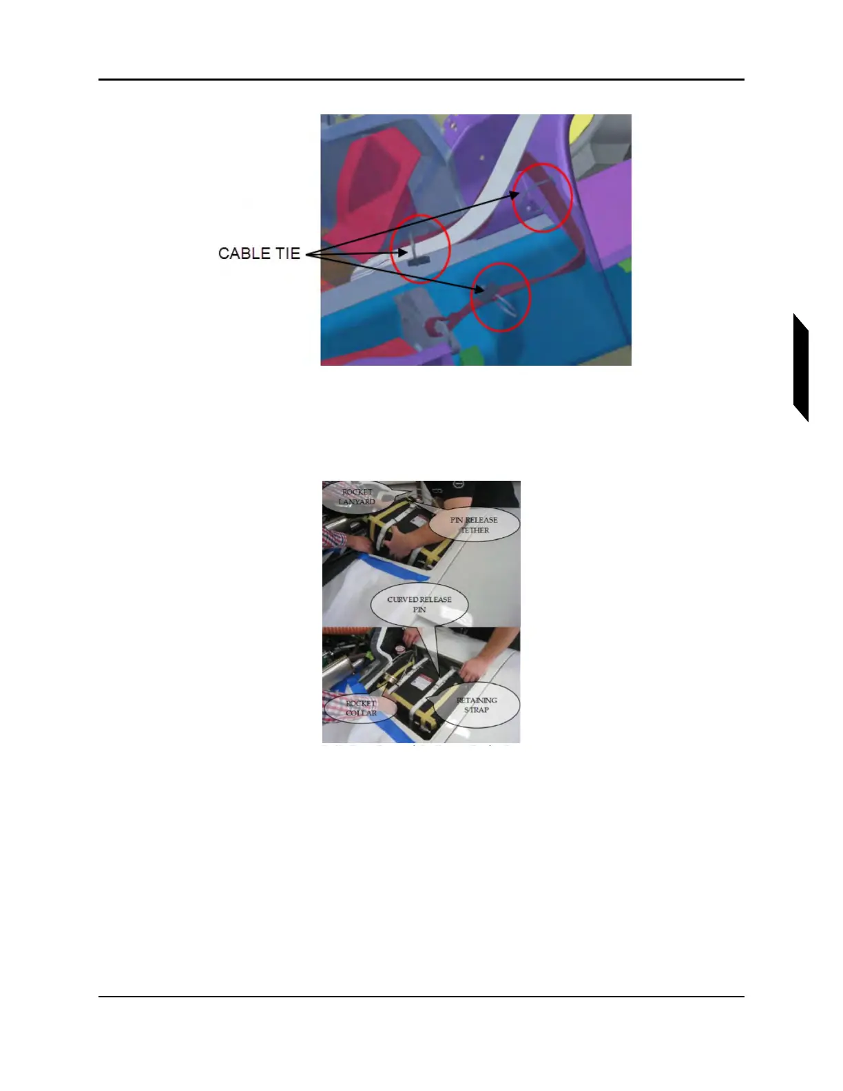
8. Install packed parachute assembly (Item 4) into parachute bay. Pin Release Tether and Retaining
straps are shown below, attached to deployment bag. Rocket collar and lanyards can also be
seen.
FIGURE 19-13
HARNESS ROUTING, AFT, PORT HARNESS TO PARACHUTE BAY
9. Connect harnesses with 1/2” quick link. Riser can also be seen on the right side of the deploy-
ment bag. Apply LOCTITE Blue 242 threadlocker to the threads before closing the gates. A
torque of 20 lb-ft to shut the quick link. Since this product does not have a standard torque value,
ensure that all threads are engaged. Finally, check that hardware is secure.