19-28 ICON PARACHUTE SYSTEM (IPS) / EXTRACTION ROCKET
ICON A5 / MAINTENANCE MANUAL CHANGE C1
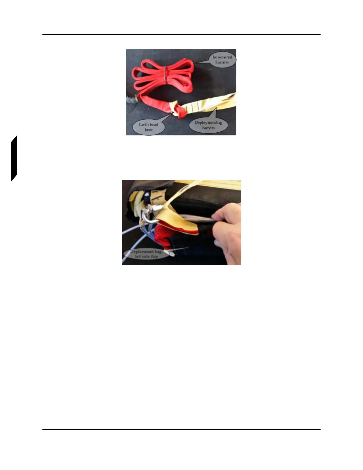
FIGURE 19-20
INCREMENTAL HARNESS TO DEPLOYMENT BAG STRAP
6. All items are secured under the left side flap of the deployment bag, using the installed Velcro
®
fasteners at the top side of the deployment bag.
FIGURE 19-21
DEPLOYMENT BAG, LEFT SIDE FLAP
7. Connect rocket collar to the rocket tube. Insert and tighten screws, screw, 8-32 x 3/4, Special.
These screws have been manufactured to shear when rocket is fired. Apply a small amount of
LOCTITE Blue 242 threadlocker to threads. Torque fasteners to 5 in-lbs.