ICON PARACHUTE SYSTEM (IPS) / ACTIVATION SYSTEM 19-35
CHANGE C1 ICON A5 / MAINTENANCE MANUAL
Level of Certification
LSA-RM
Task Specific Training Required
No
Special Tools Required
None
Parts Required
ICA009677 (FLAG, REMOVE BEFORE FLIGHT, RED CLOTH, 1.5X4.5)
MS21043-4 (NUT, SLFKG, RDC HEX, CRES, .250-28)
TY24MX_01 (CABLE-TIE, NYLON 6-6, 30LB, 5.50, TY-RAP .5 DIA)
Aircraft System and Number
16-ICON Parachute System (IPS)
Consumables
None
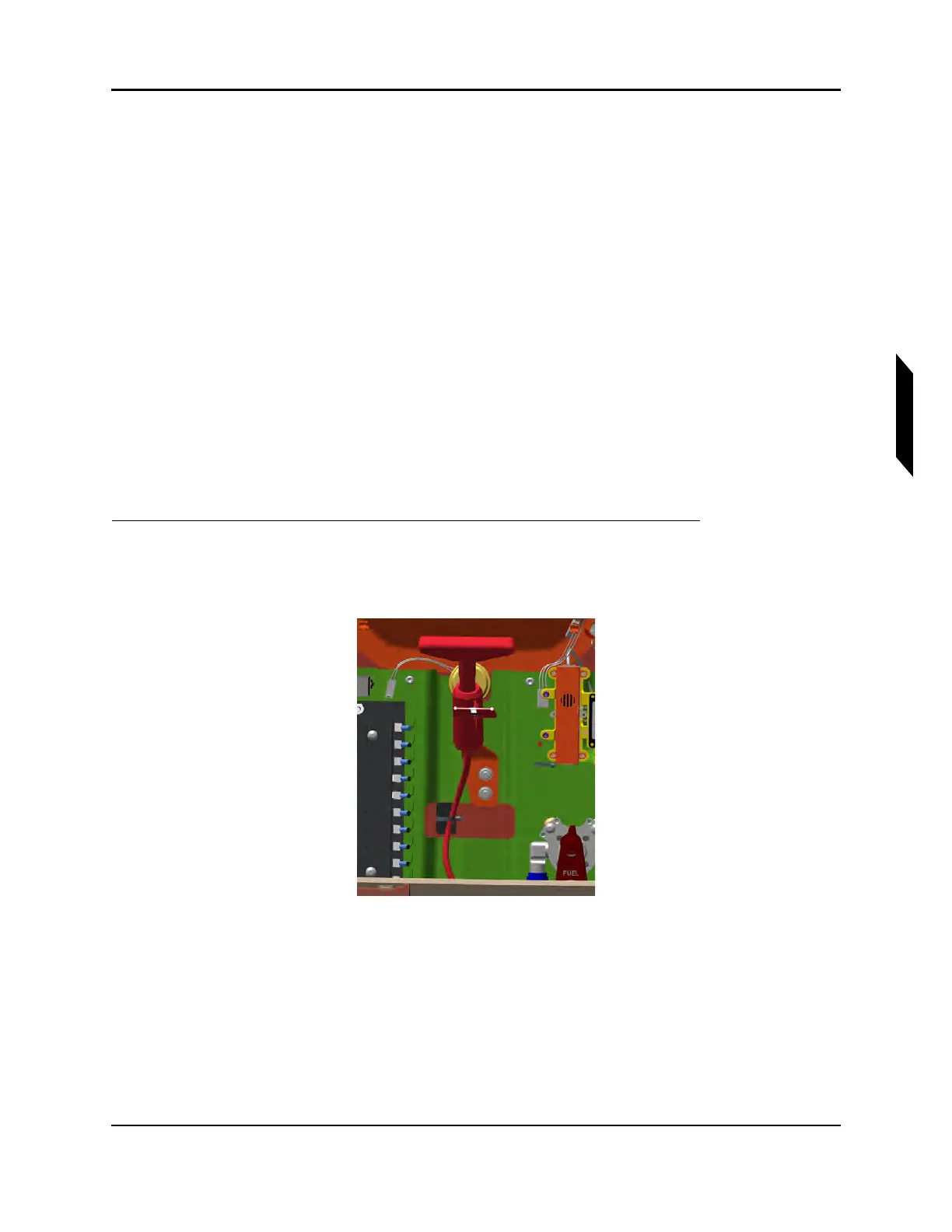
1. Fasten the activation handle to the overhead console by position the handle tang in line with the
two Click Bond studs and securing with self-locking hex nuts. Place safety pin with ‘REMOVE
BEFORE FLIGHT’ flag into activation handle.
FIGURE 19-27
ACTIVATION HANDLE, COCKPIT INSTALLATION
2. Route the rest of the activation assembly through the forward main bulkhead. Be sure that flight
controls, engine controls, electrical lines and hydraulic lines are free and clear of the activation
cable.
3. Securing activation cable. Apply first cable tie and secure the activation housing to the cable tie
mount. Cable tie mount is located on the underside of the center wing skin.