Schematic Checklist
198 Design Guide
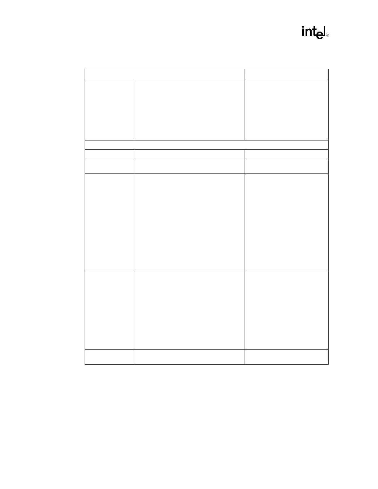
Cable Detect • Host Side/Device Side Detection
(recommended method):
– Connect IDE pin PDIAG#/CBLID# to an
ICH3-S GPIO pin. Connect a 10 k
Ω
resistor to GND on the signal line.
• Device side detection:
– Connect a 0.047 µF capacitor from IDE
pin PDIAG#/CBLID to GND. No ICH3-S
connection.
• The 10 k
Ω resistor to GND
prevents GPI from floating if no
devices are present on either
IDE interface. Allows use of
3.3 V and 5 V tolerant GPIOs.
• Refer to Section 9.1.2.1.
NOTE: All ATA66/ATA100 drives will
have the capability to detect cables.
Interrupt Interface
APICCLK • Pull-down directly to GND.
APICD[1:0] • Use 10 k
Ω ± 5% pull-down resistor to
Ground.
PIRQ[D:A]# • These signals require a pull-up resistor.
• Recommend a 2.7 k
Ω ± 5% pull-up resistor
to VCC_5 or an 8.2 k
Ω ± 5% pull-up resistor
to VCC_3.3.
• Each PIRQx# line has a
separate Route Control
Register. In APIC mode, these
signals are connected to the
internal I/O APIC in the
following fashion:
– PIRQ[A]# is connected to
IRQ16.
– PIRQ[B]# is connected to
IRQ17.
– PIRQ[C]# is connected to
IRQ18.
– PIRQ[D]# is connected to
IRQ19.
This frees the ISA interrupts.
PIRQ[H:E]#/
GPIO[5:2]
• These signals require a pull-up resistor.
• Recommend a 2.7 k
Ω ± 5% pull-up resistor
to VCC5 or an 8.2 k
Ω ± 5% pull-up resistor
to VCC3_3.
• These signals are connected to
the internal I/O APIC in the
following fashion:
– PIRQ[E]# is connected to
IRQ20.
– PIRQ[F]# is connected to
IRQ21.
– PIRQ[G]# is connected to
IRQ22.
– PIRQ[H]# is connected to
IRQ23.
This frees the ISA interrupts.
SERIRQ • External weak (8.2 k
Ω ± 5%) pull-up resistor
to VCC3_3 is recommended.
• Open drain signal.
Table 13-3. Intel
®
ICH3-S Schematic Checklist (Sheet 3 of 8)
Checklist Items Recommendations Comments