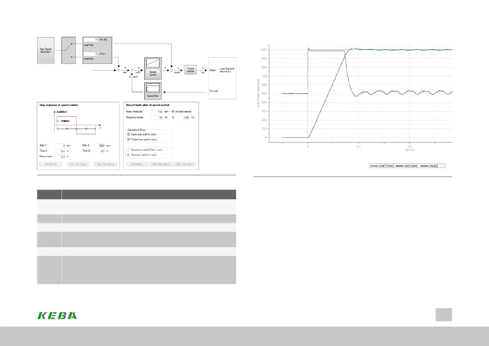
Image 7.26: “Advanced analysis of the speed controller” screen
No. Action
1
Thespeedandtimesettingsaregeneratedautomaticallyfromthemotor
data.
2 ISDSHandENPO(hardwareenable)mustbesetto"High".
3 Click"Starttestsignal"button
4
Observethesafetynotice:Whenyouconfirmthesafetynoticeastep
responseisexecuted.
5 Theoscilloscopeissetautomatically.
6
Thefastertheactualvalueapproachesthesetpoint,themore
dynamicallythecontrollerisset.Theovershootoftheactualvalueshould
notbemorethan5-10%ofthesetpoint(generalfigure)duringthe
settlingprocess.
Table 7.18: Instructions for optimization of the speed controller
ID No.: 0842.26B.5-01Date: 09.2020
ServoOne- Device Help
140
7 Control
Image 7.27: Step response to rated speed
Creating the transfer function
The oscilloscope automatically records the amount and phase response of the
controller according to the controller settings. This produces an initial estimate of the
control quality.
To determine the transfer function the noise amplitude (motor rated current) and the
sampling time (default 0.125 ms) must be specified. Click the "Start Test Signal"
button.