MD-11 Flight Crew Operations Manual
k
Electrical -
Controls and Displays
Elec.30.10
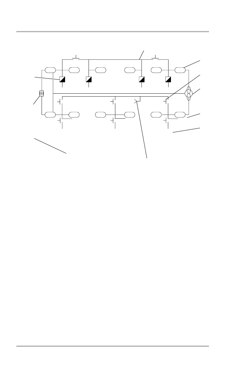
SD Synoptic
1. Schematic Lines
Schematic lines representing power buses are shown as solid white lines at all
times.
2. Relays
Relays are shown green when closed and are white when open during normal
operation. Relays are amber when open due to a fault.
3. Buses
Buses are shown in green with the bus name inside in white. If off, the buses
turn amber and OFF will appear in amber above the bus.
4. Air Driven Generator (ADG)
The ADG and all connecting lines are shown in white. When in use, the ADG
symbol is shown in green with its voltage and frequency shown to the left of
the ADG symbol in white. If ADG voltage and/or frequency are out of limits,
the associated parameter will be boxed and amber. If no valid data is
available, the data will be removed.
7
ELECTRICAL
LE
1
2
3
RE
GS
OFF
28
0.38
28
0.63
28
0.78
28
1.00
APU
EXT PWR
GLY PWR
115 V
114 V
115 V
400 HZ
399 HZ
400 HZ
0.60 LOAD
EXT PWR
115/400
LE
1
2
3
RE
GS
OFF
OFF
APU PWR
115/400
0.82
95/400
0.45
115/400
1.00
(G)
FAULT(G)
3
4
5
6
2
8
9
10
DISC(G)
28
-50
DB1-2-1759
October 02, 2006