MD-11 Flight Crew Operations Manual
k
Instrumentation and Navigation -
Controls and Displays
Inst.30.13
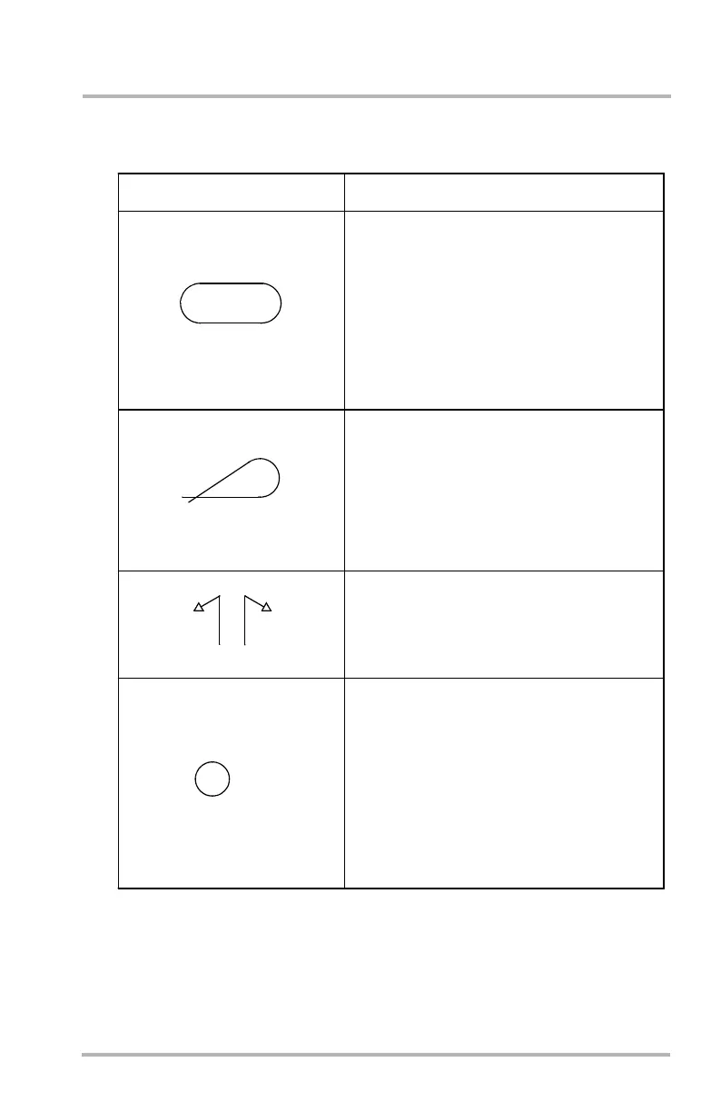
ND Flight Plan Symbology (Sheet 3)
LB1-3-0319
U.S.
SELECTED
EXPLANATION
Holding Pattern
Holding patterns are displayed using a race-
track shaped symbol. For smaller ranges (80 n
mi or less), the racetrack symbol is replaced
with arcs and lines representing the actual
flight path along the holding pattern. Holding
patterns are generated by the FMS via the
HOLD page. The pilot may select a holding
pattern at present position (PPOS) or at a
defined waypoint.
Procedure Turns
Procedure turns are displayed as a standard
tear drop pattern. For smaller ranges (40 n mi
or less) the procedure turn is replaced with
arcs and lines representing the actual flight
path in the procedure turn. Procedure turns
are generated by the FMS through the PROC
TURN page.
Turn Direction
Turn direction symbols are displayed in amber
to indicate which direction to make a course
change when it is not obvious such as a leg
sequence discontinuity or a large course change.
Speed Limit/Constraint (Climb or Descent)
Altitude, speed limit, and a circle symbol rep-
resent the lateral path point the FMS predicts
the climb or descent speed limit will be reached.
Data is displayed in magenta.
A speed limit may be entered or altered via
the LEGS page on the MCDU. An altitude
speed limit is defaulted into the flight plan as
250 knots at or below 10000 feet. Altitude
speed limits may be altered or cleared.
10000
250KT
October 02, 2006