dsPIC30F Family Reference Manual
DS70053C-page 6-32 © 2004 Microchip Technology Inc.
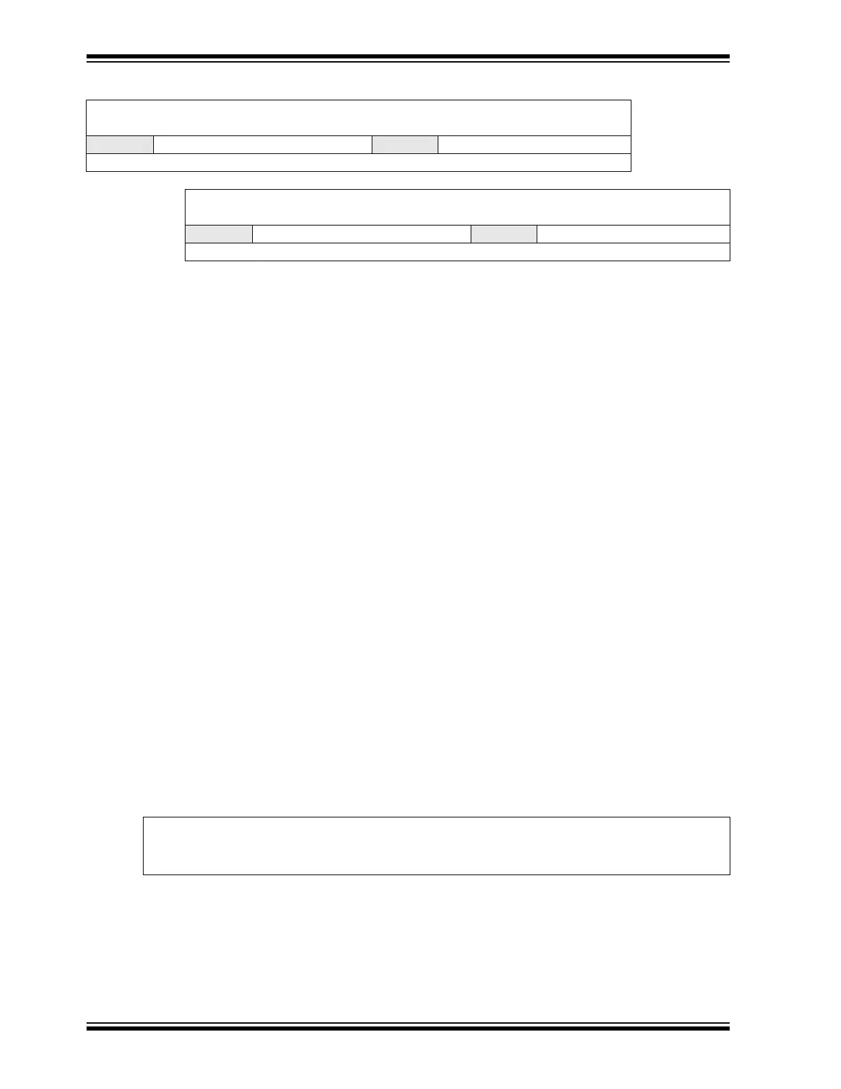
Register 6-13: IPC2: Interrupt Priority Control Register 2
Upper Byte:
U-0 R/W-1 R/W-0 R/W-0 U-0 R/W-1 R/W-0 R/W-0
— ADIP<2:0> — U1TXIP<2:0>
bit 15 bit 8
Lower Byte:
U-0 R/W-1 R/W-0 R/W-0 U-0 R/W-1 R/W-0 R/W-0
— U1RXIP<2:0> — SPI1IP<2:0>
bit 7 bit 0
bit 15 Unimplemented: Read as ‘0’
bit 14-12 ADIP<2:0>: A/D Conversion Complete Interrupt Priority bits
111 = Interrupt is priority 7 (highest priority interrupt)
•
•
•
001 = Interrupt is priority 1
000 = Interrupt source is disabled
bit 11 Unimplemented: Read as ‘0’
bit 10-8 U1TXIP<0>: UART1 Transmitter Interrupt Priority bits
111 = Interrupt is priority 7 (highest priority interrupt)
•
•
•
001 = Interrupt is priority 1
000 = Interrupt source is disabled
bit 7 Unimplemented: Read as ‘0’
bit 6-4 U1RXIP<2:0>: UART1 Receiver Interrupt Priority bits
111 = Interrupt is priority 7 (highest priority interrupt)
•
•
•
001 = Interrupt is priority 1
000 = Interrupt source is disabled
bit 3 Unimplemented: Read as ‘0’
bit 2-0 SPI1IP<2:0>: SPI1 Interrupt Priority bits
111 = Interrupt is priority 7 (highest priority interrupt)
•
•
•
001 = Interrupt is priority 1
000 = Interrupt source is disabled
Legend:
R = Readable bit W = Writable bit U = Unimplemented bit, read as ‘0’
-n = Value at POR ‘1’ = Bit is set ‘0’ = Bit is cleared x = Bit is unknown