122 CYLINDER HEAD AND VALVE TRAIN
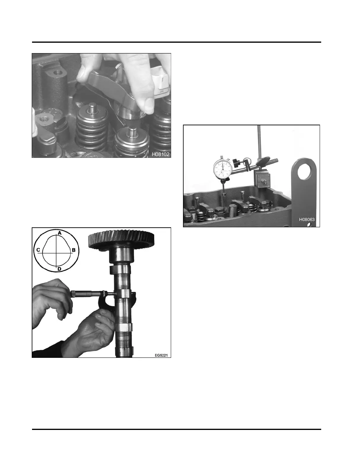
Figure 139 Removing the valve bridge
5. If removing valve bridges, mark all valve bridges
for installation (original orientation) later on.
Measuring Cams haft Lift
Figure 140 Measuring cam lobes with
micrometer
NOTE: If a complete engine overhaul is scheduled,
camshaft lobe wear can be determined by measuring
lobes (Checking Camshaft Lobes and Journals, page
263) with a micrometer after the camshaft is removed.
At this stage of disassembly, determine the
appropriate stage of camshaft inspection. If this
is not a complete engine overhaul, measure camshaft
lobe lift now using the following procedure.
Figure 141 Mounting magnetic base dial
indicator
1. Mount a magnetic base dial indicator onto the
cylinder head.
2. Place dial indicator tip on top of push rod and
rotate engine until push rod is at its lowest point
of travel (base circle), then “zero” indicator.
EGES-265-2
Read all safety instructions in the "Safety Information" section of this manual before doing any procedures.
Follow all warnings, cautions, and notes.
© 2009 Navistar, Inc.
 Loading...


