176 FRONT COVER AND RELAT ED COMPONENTS
Front Cover (Rear Half)
NOTE: If the (rear half) of a Generation 1 front
cover assembly needs to be replaced, install a new
Generation 2 front cover assembly (front and rear
half). The (rear half) of the Generation 1 front cover
assembly is not available for service.
NOTE: Generation 1 (rear half) front covers include a
water pump wear plate.
1
2
3
4
2
H06079
5
5
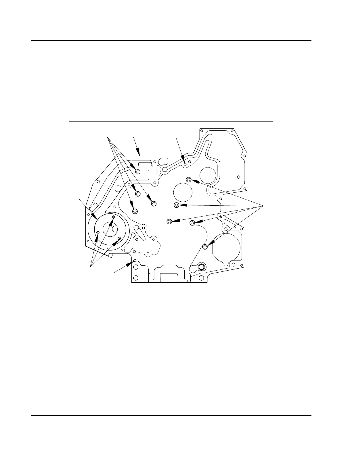
Figure 239 Front cover
mounting bolts – rear half (Generation 1)
1. Front cover assembly
(rear half)
2. Special hex flange bolt
,M8x20
(9)
3. Flat head hex socket,
M5 (3)
4. Wear plate
5. Dowel pin locations
1. Remove the camshaft
or camshaft assembly
before removing fr
ont cover (rear half). See
“Crankcase, Cran
kshaft, and Camshaft” section
in this manual for
removal procedure.
2. Remove nine mount
ing bolts (M8 x 20) that secure
the rear half of th
e front cover to the crankcase.
Pull cover straight
outward to slide dowels out of
the crankcase. The
se dowels are retained in the
rear half of the fr
ont cover.
3. Remove the oil and c
oolant gaskets from the rear
half of the front c
over and discard.
EGES-265-2
Read all safety instructions in the "Safety Information" section of this manual before doing any procedures.
Follow all warnings, cautions, and notes.
© 2009 Navistar, Inc.
 Loading...


