FRONT COVER AND RELATED COMPONENTS 193
Fan Drive
Table 18 Fan Drive Mounting B olt Sizes
Fan drive mounting configuration
Bolt size Torque
Quantity
High-mount, Horton (20 in)
M8 x 1.25 x 30
26 N·m (19 lbf·ft)
4
High-mount, Horton (18.3 in)
M8 x 1.25 x 30
26 N·m (19 lbf·ft)
4
Mid-mount, Horton (16.2 in)
M8 x 1.25 x 30
26 N·m (19 lbf·ft)
4
Low-mount (Horton 12.2 in)
M8 x 1.25 x 30
26 N·m (19 lbf·ft)
4
M8 x 1.25 x 30
Standard
2
High-mount (spin-on)
M8 x 1.25 x 65
Standard
2
M8 x 1.25 x 30
Standard
2
Mid-mount (spin-on)
M8 x 1.25 x 65
Standard
2
Low-mount (bolt-on and spin-on)
M8 x 1.25 x 65
Standard
4
NOTE: The table located at the back of this se
ction
covers fan drive configurations diameters a
nd ratios
(Table 19).
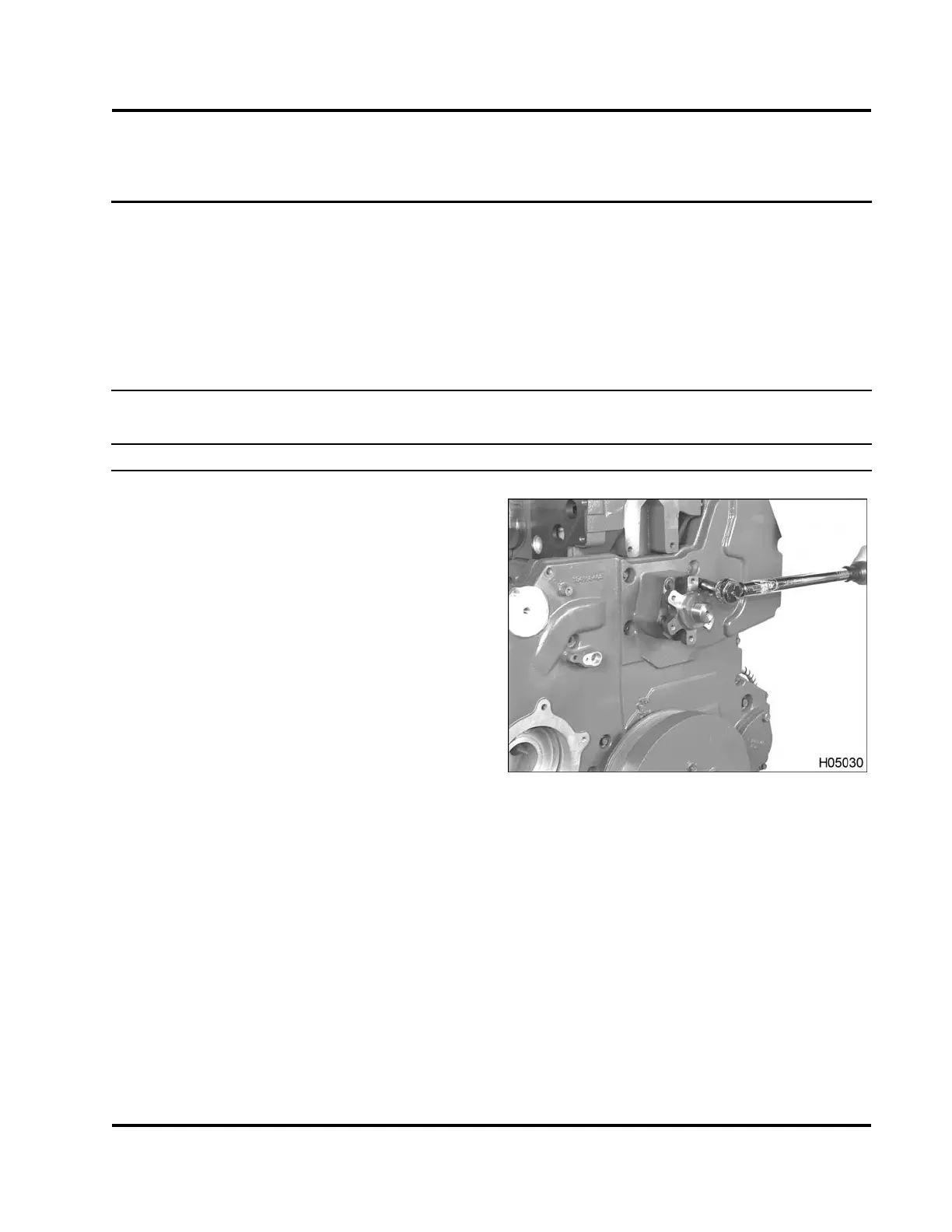
1. Install fan hub assembly.
NOTE: The standard fan hub assembly is s
erviced
as a unit. The assembly is made up of the f
ollowing
nonserviceable items:
• Fan and pulley mounting hub
• Fan bearing hub
• Bearing assembly
•M10x70bolt
• Fan bearing retainer
Figure 267 Torquing the fan dr
ive mounting
bolts (typical)
2. Install the hex flange bol
ts required (Table 18)
and tighten to the standa
rd torque value (General
Torque Guidelines, pag
e 445), unless otherwise
noted(Table20).
EGES-265-2
Read all safety instructions in the "Safety Information" section of this manual before doing any procedures.
Follow all warnings, cautions, and notes.
© 2009 Navistar, Inc.
 Loading...


