FRONT COVER AND RELATED COMPONENTS 181
Mounting Bolts (Rear Half)
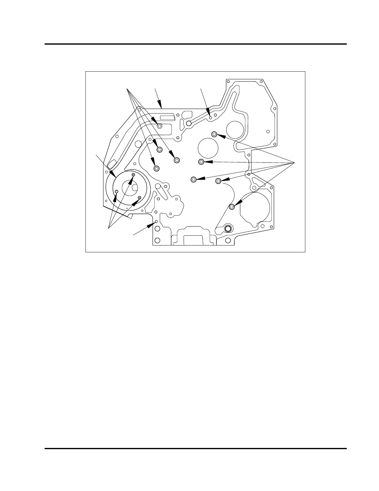
1
2
3
4
2
H06079
5
5
Figure 246 Front cover mounti
ng bolts – rear half
1. Front cover assembly (rea
rhalf)
2. Special hex flange bolt, M8 x
20
(9)
3. Flat head hex socket, M5 (3
)
4. Wear plate
5. Dowel pin
1. Position the rear half of t
he front cover onto the
crankcase and install a
ll nine mounting bolts
finger tight. Then tigh
ten the mounting bolts to
the special torque va
lue (Table 20).
2. Install the camshaft or ca
mshaft assembly after
installing front cover
(rear half). See “Crankcase,
Crankshaft, and Camsh
aft” section in this manual
for removal procedur
e.
EGES-265-2
Read all safety instructions in the "Safety Information" section of this manual before doing any procedures.
Follow all warnings, cautions, and notes.
© 2009 Navistar, Inc.
 Loading...


