346 FUEL SYSTEM
3. Loosen jam nuts on each elbow.
4. Remove 70 and 90 degree elbows.
5. Remove and discard each elbow back-up ring and
O-rings.
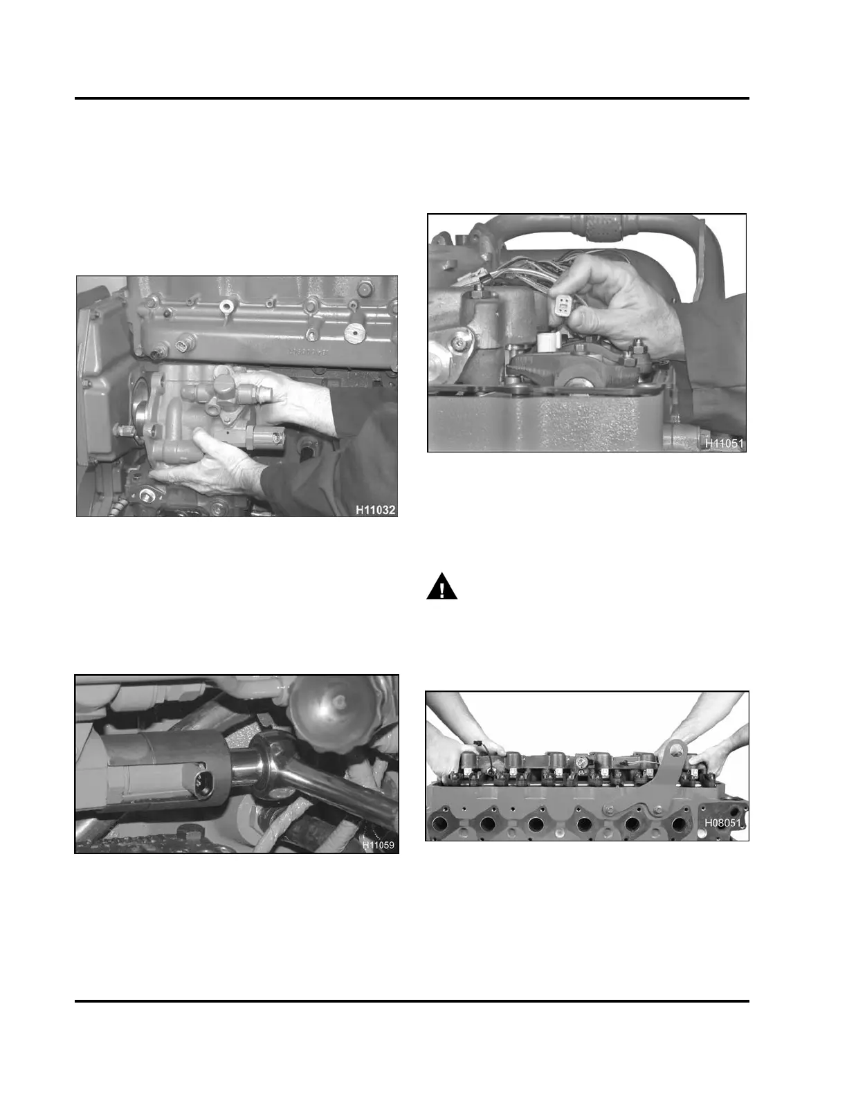
High-pressure Pump and IPR Valve
Figure 539 Removing the high-pressure pump
assembly
1. Remove two bolts (M8 x 100) behind pump and
two (M8 x 30) bolts securing the high-pressure
pump to the front cover. Remove pump assembly
and discard seal.
Figure 540 Removing the IPR valve
2. Use an IPR removal / installation tool (Table 48)
to remove the IPR valve. Check inlet screen for
restrictions. Remove O-rings and discard.
High-pressure Oil R ail Assembly
1. Remove valve cover. See (Valve Cover, page120)
in the “Cylinder Head and Valve Train” section of
this manual.
Figure 541 Removing the injector harness
connector
2. Disconnect the injector harness conn
ector at the
top of each injector.
WARNING: To prevent personal injury or
death, get assistance to remove and install the
high-pressure oil rail assembly.
3. Remove 12 bolts (M8 x 90) securing
high-pressure oil rail to cylinder head.
Figure 542 Removing
the high-pressure oil rail
4. Remove all bolts and lift high-pressure oil rail
up just enough to drain as much oil out of
high-pressure oil rail before lifting it away from
cylinder head.
EGES-265-2
Read all safety instructions in the "Safety Information" section of this manual before doing any procedures.
Follow all warnings, cautions, and notes.
© 2009 Navistar, Inc.
 Loading...


