198 FRONT COVER AND RELAT ED COMPONENTS
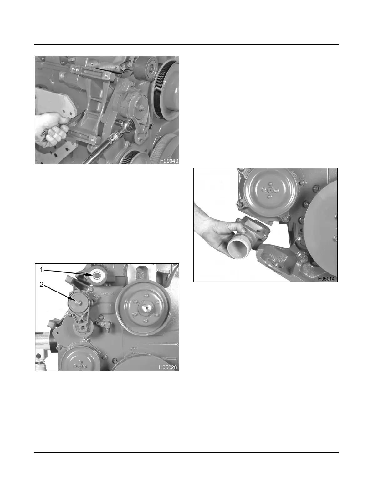
Figure 277 Torquing the alternator bracket bolts
3. Tighten all alternator bracket bolts to the standard
torque value (General Torque Guidelines, page
445).
4. Install harness routing guide and secure guide
with an M8 bolt.
Flat Idler Pulley and Automatic Belt Tensioner
Figure 278 Flat idle
r pulley and automatic belt
tensio ner
1. Flat idler pulley a
ssembly mounting bolt, M10 x 80
2. Automatic belt tens
ioner assembly mounting bolt,
M10 x 80
1. Install M10 x 80 bolt through flat idler pulley
assembly and into the water supply housing.
Tighten bolt to the standard torque value (General
Torque Guidelines, page445).
2. Install M10 x 80 bolt through the automatic belt
tensioner assembly to the front cover assembly
and tighten to the special torque (Table 20).
Water Inlet Elbow, Water Outlet Tube, and
Thermostat
1. Install a water inlet gasket into the machined
recess at the front cover.
Figure 279 Water inlet elbow
2. Install water inlet (side port) elbow.
3. Install and tighten three hex flange bolts (M8 x
30) to the standard torque value (General Torque
Guidelines, page445).
NOTE: The thermostat seal cannot be purchased
separately. It is only available with the thermostat
assembly.
EGES-265-2
Read all safety instructions in the "Safety Information" section of this manual before doing any procedures.
Follow all warnings, cautions, and notes.
© 2009 Navistar, Inc.
 Loading...


