138 CYLINDER HEAD AND VALVE TRAIN
Installation
1. Use a micrometer to measure the diameter of the
valve seat insert counterbore at two locations,
90° apart. Average the two measurements to
determine the appropriate size valve seat insert
to install.
Table 12 Valve Seat Insert Selection Chart
Available inserts (int. and
exh.)
Ave. dia. of intake counterbore Ave. dia. of exhaust counterbore
Standard 40.119 - 40.170 mm (1.5795 - 1.5815
in)
37.478 - 37.529 mm (1.4755 - 1.4775
in)
Oversize - 0.05 mm (0.002 in) 40.170 - 40.221 mm (1.5815 - 1.5835
in)
37.529 - 37.579 mm (1.4775 - 1.4795
in)
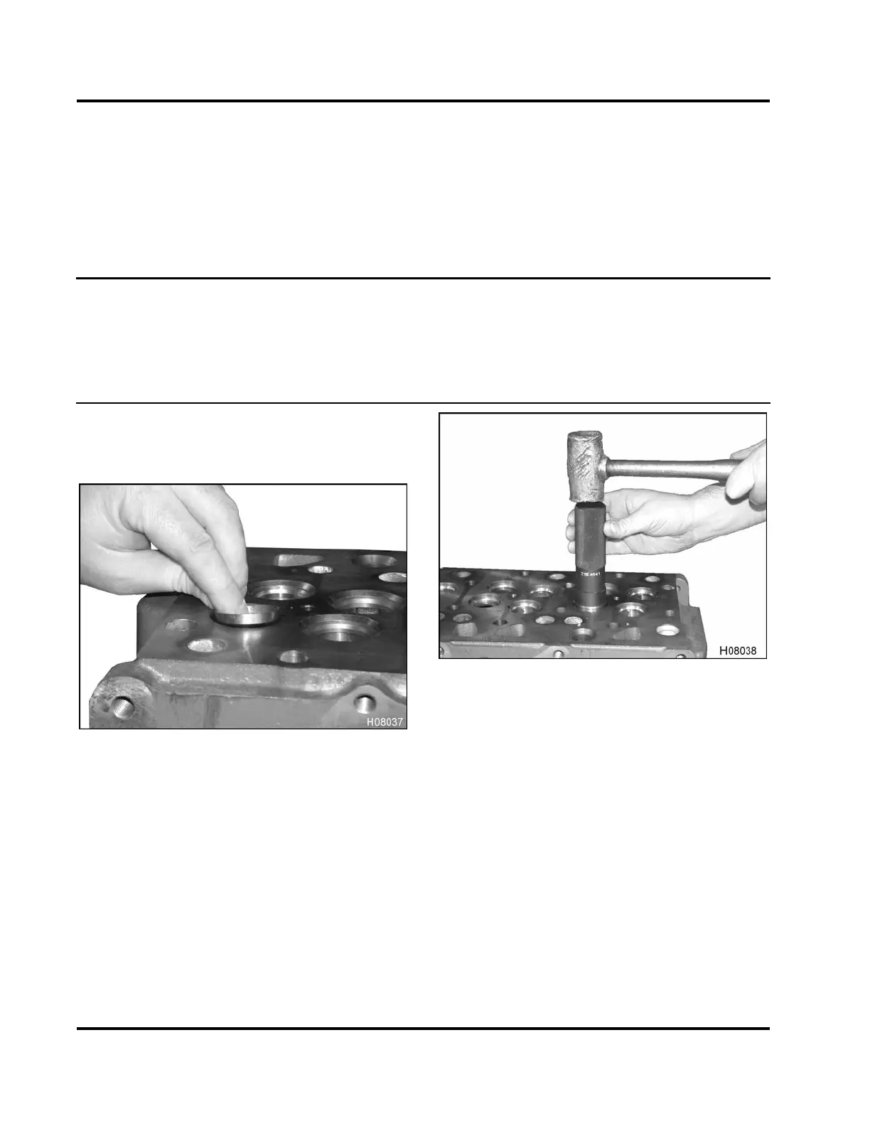
2. Chill the valve seat insert in a freezer for 30
minutes. This will prevent the outer layer of metal
from being shaved off during installation.
Figure 182 Placing chilled valve seat into head
3. Align insert over counterbore to avoid
misalignment.
Figure 183 Driving valve seat into place
4. Using a hammer and valve seat installation tool
drive the valve seat into place until it is fully
seated. See Cylinder head and valve special
service tools (Table 17).
5. Grind new valve seats to the specified angles and
widths, see Cylinder Head Specifications (Table
15) in this section.
EGES-265-2
Read all safety instructions in the "Safety Information" section of this manual before doing any procedures.
Follow all warnings, cautions, and notes.
© 2009 Navistar, Inc.
 Loading...


